Current Sensors » ACS72981 Current Sensor Carriers » ACS72981 Current Sensor Compact Carriers »
ACS72981LLRATR-100U5 Current Sensor Compact Carrier 0A to 100A, 5V

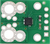
This is the compact version of a simple carrier for Allegro’s ACS72981LLRATR-100U5 Hall effect-based, electrically isolated current sensor, which offers a low-resistance (~0.2 mΩ) current path and a high 250 kHz bandwidth for fast response times.
| Part Suffix | Range | Supply Voltage | Sensitivity @ 5 V | Zero Point @ 5 V | Size |
|---|---|---|---|---|---|
| 100U5 | 0-100 A (unidirectional) | 4.5 V to 5.5 V | 40 mV/A | 0.5 V | 0.7″×0.8″ |
Alternatives available with variations in these parameter(s): version size Select variant…
 Compare all products in ACS72981 Current Sensor Compact Carriers.
| Description | Specs (12) | Pictures (13) | Resources (6) | FAQs (0) | On the blog (0) |
|---|
Overview
 |
 |
ACS72981 Current Sensor Compact Carrier (top) and Large Carrier (bottom) size comparison. |
|---|
We are offering these breakout boards with support from Allegro Microsystems as an easy way to use or evaluate their ACS72981xLR Hall effect-based, electrically isolated current sensors; we therefore recommend careful reading of the ACS72981 datasheet before using this product. The following list details some of the sensor’s key features:
- Hall effect-based sensor with electrically isolated current path allows the sensor to be inserted anywhere along the current path and to be used in applications that require electrical isolation.
- Differential Hall sensing rejects common-mode fields, so the orientation of the sensor relative to uniform external magnetic fields (e.g. the Earth’s magnetic field) has less effect on the measurement.
- The conductive path internal resistance is typically 0.2 mΩ, and the PCB is made with 6 layers of 2-oz copper, so very little power is lost in the module.
- High-bandwidth 250 kHz analog output voltage proportional to AC or DC currents
- Less than 2 µs response time.
- Integrated digital temperature compensation circuitry allows improved accuracy over the full operating temperature range.
- Carrier boards, available in compact and large sizes, offer a variety of ways to insert it into the current path and 0.1″-pitch (breadboard compatible) power, ground, and output pins.
- 3.3V and 5V versions available.
- Unidirectional and bidirectional versions available.
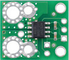
The connection points are labeled on the bottom silkscreen. The silkscreen also shows the direction that is interpreted as positive current flow via the +i arrow.
The following table lists the available ACS72981 carrier options:
| Pololu Item # |
Part Suffix | Supply Voltage (V) |
Current Range | Sensitivity @ Nominal Vcc (mV/A) |
Zero Point @ Nominal Vcc (V) |
Size | Price | ||
|---|---|---|---|---|---|---|---|---|---|
 Large Carrier |
#5270 | 050B3 | 3.0 to 3.6 (3.3 nominal) |
Bidirectional | ±50 A | 26.4 | 1.65 | 1.4″×1.2″ | $12.95 |
| #5273 | 100B3 | ±100 A | 13.2 | ||||||
| #5277 | 150B3 | ±150 A | 8.8 | ||||||
| #5272 | 050U3 | Unidirectional | 0-50 A | 52.8 | 0.33 | ||||
| #5275 | 100U3 | 0-100 A | 26.4 | ||||||
| #5279 | 150U3 | 0-150 A | 17.6 | ||||||
| #5271 | 050B5 | 4.5 to 5.5 (5 nominal) |
Bidirectional | ±50 A | 40 | 2.5 | |||
| #5274 | 100B5 | ±100 A | 20 | ||||||
| #5278 | 150B5 | ±150 A | 13.3 | ||||||
| #5276 | 100U5 | Unidirectional | 0-100 A | 40 | 0.5 | ||||
 Compact Carrier |
#5250 | 050B3 | 3.0 to 3.6 (3.3 nominal) |
Bidirectional | ±50 A | 26.4 | 1.65 | 0.7″×0.8″ | $9.95 |
| #5253 | 100B3 | ±100 A | 13.2 | ||||||
| #5257 | 150B3 | ±150 A | 8.8 | ||||||
| #5252 | 050U3 | Unidirectional | 0-50 A | 52.8 | 0.33 | ||||
| #5255 | 100U3 | 0-100 A | 26.4 | ||||||
| #5259 | 150U3 | 0-150 A | 17.6 | ||||||
| #5251 | 050B5 | 4.5 to 5.5 (5 nominal) |
Bidirectional | ±50 A | 40 | 2.5 | |||
| #5254 | 100B5 | ±100 A | 20 | ||||||
| #5258 | 150B5 | ±150 A | 13.3 | ||||||
| #5256 | 100U5 | Unidirectional | 0-100 A | 40 | 0.5 | ||||
Details for item #5256
|
|


This compact carrier features the ACS72981LLRATR-100U5, which is intended for nominal 5 V operation and is designed for unidirectional input current from 0 A to 100 A. This version can be visually distinguished from the other versions by the “5V U10” printed on the bottom side, as shown in the left picture above.
| Part Suffix | Range | Supply Voltage | Sensitivity @ 5 V | Zero Point @ 5 V | Size |
|---|---|---|---|---|---|
| 100U5 | 0-100 A (unidirectional) | 4.5 V to 5.5 V | 40 mV/A | 0.5 V | 0.7″×0.8″ |
A larger carrier is also available for this sensor IC with room for larger connectors and thicker wires for the high-current path, offering different ways to use or evaluate this current sensor.
Using the sensor
 |
This sensor has five required connections: the input current (IP+ and IP-), logic power (VCC and GND), and the sensor output (VIOUT).
The sensor requires a supply voltage of 4.5 V to 5.5 V to be connected across the VCC and GND pads, which are labeled on the bottom silkscreen. The sensor outputs a ratiometric analog voltage on VIOUT that has a zero point at VCC/10 and increases by 40 mV × (VCC/5 V) per amp of input current:
``V_"IOUT" = V_"CC" / 10 + 0.04 text(V)/text(A) * V_"CC" / (5 text(V)) * I_"P" = V_"CC" * (1/10 + I_"P" / (125 text(A)))``
``I_"P" = 125 text(A) * (V_"IOUT" / V_"CC" – 1/10)``
The VIOUT, VCC, and GND pins work with 0.1″-pitch header pins and are compatible with standard solderless breadboards.
 |
You can insert the board into your current path in a variety of ways. For typical high-current applications, you can solder wires directly to the through-holes that best match your wires, or you can use solderless ring terminal connectors, as shown in the pictures below. The largest through-holes are big enough for 8 AWG wires or #6 or M3.5 screws, and the second-largest through-holes (and mounting holes) are sized for 12 AWG wires or #2 or M2 screws. Holes with 0.1″, 3.5 mm, and 5 mm spacing are also available as shown in the diagram above for connecting male header pins or terminal blocks, but please note that these connection options will generally not be suitable for the kinds of high currents intended for this sensor.
|
|
||
|
|


Warning: This product is intended for use below 30 V. Working with higher voltages can be extremely dangerous and should only be attempted by qualified individuals with appropriate equipment and experience.
Schematic and dimension diagrams
 |
ACS72981 Current Sensor Carrier schematic diagram. |
|---|
The dimension diagram is available as a downloadable PDF (400k pdf).
Comparison of the Pololu current sensor carriers
We have a variety of current sensors available with different ranges, sensitivities, and features. The table below summarizes our selection of active and preferred options:
 |
 |
 |
 |
 |
 |
|
|
| ACS711 Current Sensor Carriers |
ACS71240 Current Sensor Carriers |
ACS724 Current Sensor Carriers |
ACS37220 Current Sensor Compact Carriers |
ACS37220 Current Sensor Large Carriers |
ACS72981 Current Sensor Compact Carriers |
ACS72981 Current Sensor Large Carriers |
|
| Sensor IC | Allegro ACS711KEXT |
Allegro ACS71240 |
Allegro ACS724LLCTR |
Allegro ACS37220 | Allegro ACS72981xLR | ||
|---|---|---|---|---|---|---|---|
| Vcc range (V) | 3.0–5.5 | 3.3V versions: 3.0–3.6 5V versions: 4.5–5.5 |
4.5–5.5 | 3.3V versions: 3.15–3.45 5V versions: 4.5–5.5 |
3.3V versions: 3.0–3.6 5V versions: 4.5–5.5 |
||
| Current range / sensitivity |
Bidirectional:(1) ±15.5 A / 90 mV/A ±31 A / 45 mV/A |
3.3V Bidirectional: ±10 A / 132 mV/A ±30 A / 44 mV/A ±50 A / 26.4 mV/A 5V Unidirectional: 0–50 A / 80 mv/A |
5V Bidirectional:(2) ±2.5 A / 800 mV/A ±5 A / 400 mV/A ±10 A / 200 mV/A ±20 A / 100 mV/A ±30 A / 66 mV/A ±50 A / 40 mV/A 5V Unidirectional:(2) 0–5 A / 800 mv/A 0–10 A / 400 mv/A 0–20 A / 200 mv/A 0–30 A / 133 mV/A |
3.3V Bidirectional: ±100 A / 13.2 mV/A ±150 A / 8.8 mV/A 5V Bidirectional: ±100 A / 20 mV/A ±150 A / 13.3 mV/A ±200 A / 10 mV/A |
3.3V Bidirectional: ±100 A / 13.2 mV/A ±150 A / 8.8 mV/A 5V Bidirectional: ±100 A / 20 mV/A ±150 A / 13.3 mV/A ±200 A / 10 mV/A |
3.3V Bidirectional:(1) ±50 A / 26.4 mV/A ±100 A / 13.2 mV/A ±150 A / 8.8 mV/A 3.3V Unidirectional:(1) 0–50 A / 52.8 mv/A 0–100 A / 26.4 mv/A 0–150 A / 17.6 mv/A 5V Bidirectional:(2) ±50 A / 40 mV/A ±100 A / 20 mV/A ±150 A / 13.3 mV/A 5V Unidirectional:(2) 0–100 A / 40 mv/A |
3.3V Bidirectional:(1) ±50 A / 26.4 mV/A ±100 A / 13.2 mV/A ±150 A / 8.8 mV/A 3.3V Unidirectional:(1) 0–50 A / 52.8 mv/A 0–100 A / 26.4 mv/A 0–150 A / 17.6 mv/A 5V Bidirectional:(2) ±50 A / 40 mV/A ±100 A / 20 mV/A ±150 A / 13.3 mV/A 5V Unidirectional:(2) 0–100 A / 40 mv/A |
| IC path resistance | 0.6 mΩ | 0.6 mΩ | 0.6 mΩ | 0.1 mΩ | 0.2 mΩ | ||
| PCB | 2 layers, 2-oz copper |
2 layers, 2-oz copper |
2 layers, 2- or 4-oz copper(4) |
2 layers, 2-oz copper |
6 layers, 2-oz copper |
6 layers, 2-oz copper |
6 layers, 2-oz copper |
| Max bandwidth | 100 kHz | 120 kHz | 120 kHz(3) | 150 kHz | 250 kHz | ||
| Size | 0.7″ × 0.8″ | 0.7″ × 0.8″ | 0.7″ × 0.8″ | 0.7″ × 0.8″ | 1.4″ × 1.2″ | 0.7″ × 0.8″ | 1.4″ × 1.2″ |
| Overcurrent fault output | User-configurable threshold | ||||||
| Differential sensing | |||||||
| Non-ratiometric output | |||||||
| 1-piece price | $3.49 | $3.95 | $6.95 – $7.49 | $4.95 | $7.95 | $9.95 | $12.95 |
| (1) Sensitivity when Vcc = 3.3 V; sensitivity is ratiometric. | |||||||
| (2) Sensitivity when Vcc = 5 V; sensitivity is ratiometric. | |||||||
| (3) Bandwidth can be reduced by adding a filter capacitor. | |||||||
| (4) ±50A version uses 4-oz copper PCB; all other versions use 2-oz copper. | |||||||
Related products


Home | Forum | Blog | Support | Ordering Information | Wish Lists | Distributors | BIG Order Form | About | Contact
© 2001–2024 Pololu Corporation
