Pololu Blog » Posts tagged “new products” »
Posts tagged “new products” (Page 4)
You are currently viewing a selection of posts from the Pololu Blog. You can also view all the posts.
Popular tags: community projects new products raspberry pi arduino more…
New product: VL53L5CX Time-of-Flight 8×8-Zone Distance Sensor Carrier
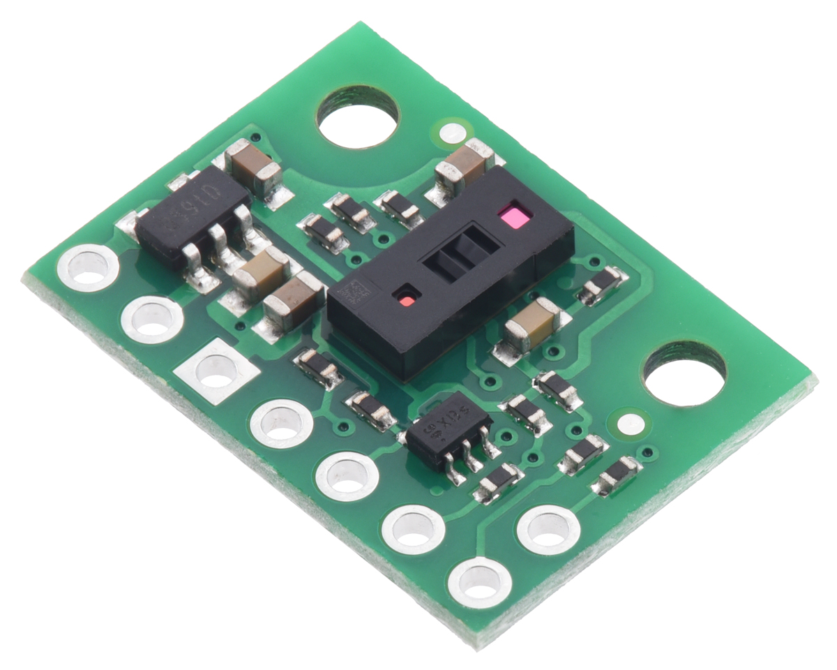 |
I’m excited to announce the release of our new VL53L5CX Time-of-Flight 8×8-Zone Distance Sensor Carrier! Over the past several years, STMicroelectronics has introduced a number of FlightSense distance sensors, starting with the VL6180X, that use time-of-flight (TOF) measurements of infrared laser light to measure distances. Each new sensor has been more capable than the last (usually offering an increased range), but the VL53L5CX is more than just another incremental upgrade. What makes the VL53L5CX really special is its ability to take readings of multiple targets across a grid of multiple zones, allowing you to generate a depth map with up to 8×8 resolution and 4 m range.
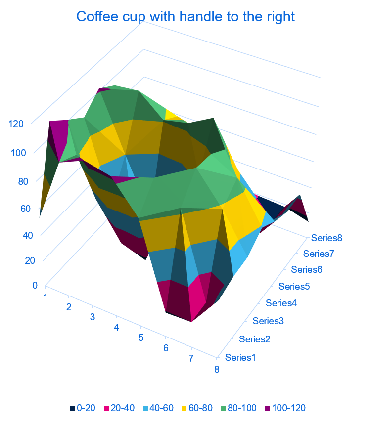 |
A plot of a coffee cup as detected by a VL53L5CX time-of-flight 8×8-zone distance sensor. |
|---|
Compared to sensors that only give a 1D measurement, the VL53L5CX does demand more from a microcontroller to support its operation as a 3D lidar. Initializing the sensor through I²C and processing its data requires a lot of RAM and program memory, so it is not practical to use the VL53L5CX with most 8-bit MCUs like the Arduino Uno. (The same was true for the VL53L3CX, which shares the VL53L5CX’s multi-target capability but does not have multi-zone capability.) We found that the Raspberry Pi Pico’s RP2040 microcontroller worked well for interfacing with the VL53L5CX, and other similarly powerful 32-bit controllers like an ESP32 should also work.
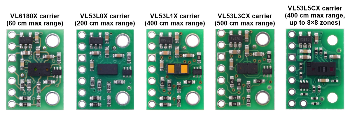 |
It’s fun to compare our VL53L5CX carrier with our other ST time-of-flight sensor boards because even though the boards are the same size (and pin-compatible), the VL53L5CX component itself is significantly bigger than its predecessors. We also switched from using 0603-size surface-mount resistors (0.06″ × 0.03″, or 1.5 mm × 0.8 mm) to 0402-size parts (1 mm × 0.5 mm) to help everything fit in the same form factor, and that makes for even more contrast with the large IC. As we refine our manufacturing abilities to let us work with more challenging parts like these, it’s nice to have more options for making things even more compact. (When can we try some 0201 parts?)
Related products

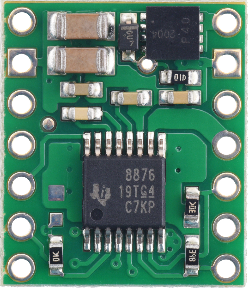
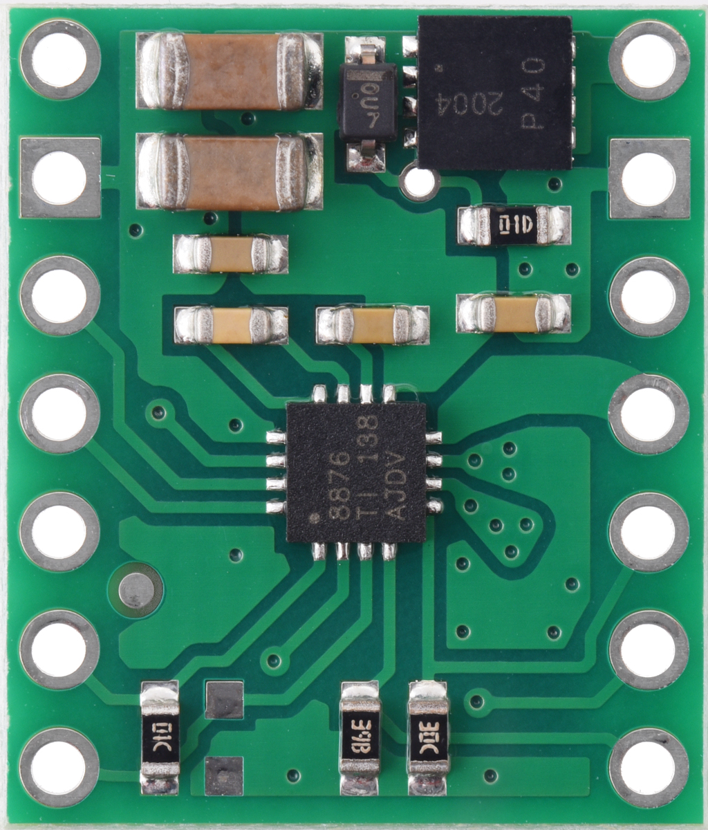
New products: DRV8874 and DRV8876 motor driver carriers
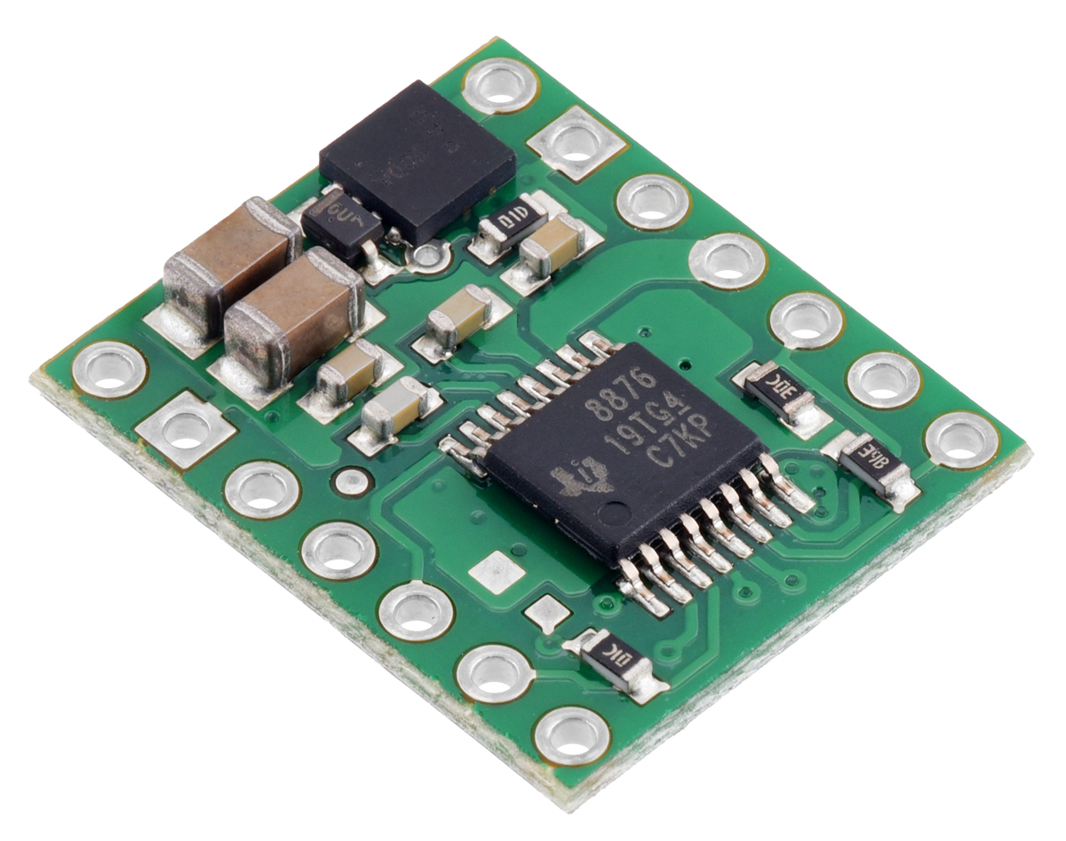 |
We’ve expanded our selection of motor drivers again with the release of some compact carrier boards for TI’s DRV8874 and DRV8876 motor drivers, which feature current sense feedback and adjustable current limiting. These three ICs and their boards are all very similar, differing mainly by the amount of current they can handle: in a TSSOP chip package, the DRV8874 delivers up to 2.1 A continuous on our carrier board and the DRV8876 does 1.3 A. The DRV8876 chip is also available in a smaller QFN package, so for a lower-current and lower-cost option, our DRV8876 (QFN) carrier can deliver 1.1 A continuously. All three versions can drive a single brushed DC motor at voltages from 4.5 V to 37 V.
|
|
|

The DRV8874 and DRV8876 drivers offer a choice of control modes that includes phase/enable (PH/EN) and direct PWM (IN/IN) as well as independent half-bridge control, which lets you drive two motors unidirectionally. With their wide operating voltage range and current sense/current limiting added in, this combination of capabilities results in some unusually versatile motor driver boards, especially considering their small size. (But if you need something that works with even higher voltages, consider our similar DRV8256E and DRV8256P carrier boards too, though those don’t provide current sense feedback.)
| Comparison of the DRV8874, DRV8876, and DRV8256 motor driver carriers | ||||
|---|---|---|---|---|
 DRV8876 (QFN) |
 DRV8876 |
 DRV8874 |
 DRV8256E DRV8256P |
|
| Motor channels: | one | |||
| Min. operating voltage: | 4.5 V | |||
| Max. operating voltage: | 37 V | 48 V | ||
| Max. continuous current(1): | 1.1 A | 1.3 A | 2.1 A | 1.9 A |
| Peak current: | 3.5 A | 6 A | 6.4 A | |
| Current sense feedback? | 2500 mV/A | 1100 mV/A | none | |
| Active current limiting: | adjustable | |||
| Size: | 0.6″ × 0.7″ | 0.6″ × 0.6″ | ||
| 1-piece price: | $7.14 | $8.15 | $11.94 | $14.31 (E) $14.31 (P) |
| 1 On Pololu carrier board, at room temperature and without additional cooling. | ||||
Related products


New product: Motoron M3S256 Triple Motor Controller Shield
 |
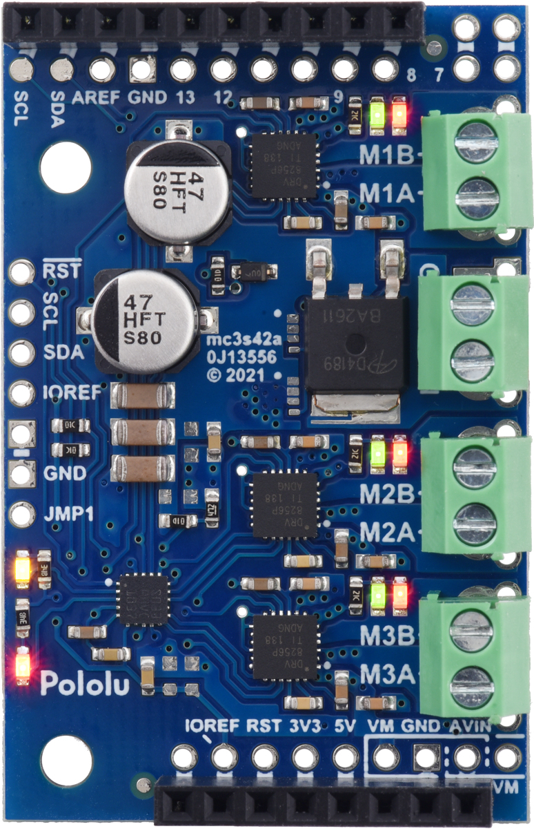 |
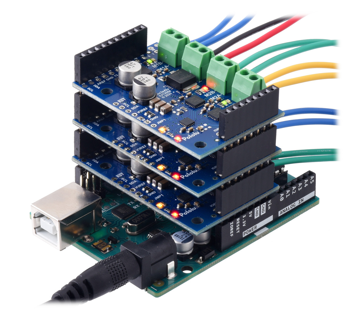
We’re excited to announce the launch of our new Motoron M3S256 Triple Motor Controller Shield! This I²C motor controller is designed to plug into an Arduino or Arduino-compatible board and control up to three bidirectional brushed DC motors at voltages from 4.5 V to 48 V with continuous currents of up to 2 A per channel. However, what really sets the Motoron apart from our other motor shields is that you can easily stack multiple boards to control even more motors at once!
Unlike basic motor driver shields that are best for driving just a few channels using the Arduino’s hardware PWM outputs, the Motoron M3S256 has its own on-board microcontroller with an I²C interface, letting you communicate with a stack of many controllers using only two I/O lines. Each Motoron can be configured to have a unique I²C target address, ensuring that every shield can be addressed individually and every motor can be controlled independently. For synchronized motion, you can even signal all the motors on several controllers to change speed at the same time with a single I²C command.
We provide an Arduino library for the Motoron that makes it easy to send it commands and configure its many settings, including motion parameters and error handling options. Working with multiple Motoron controllers is as simple as calling a few functions once you have set up their I²C addresses:
// Set up acceleration and deceleration limits for Motoron #1
mc1.setMaxAcceleration(1, 80);
mc1.setMaxDeceleration(1, 300);
mc1.setMaxAcceleration(3, 50);

// Set up acceleration and deceleration limits for Motoron #2
mc2.setMaxAcceleration(2, 50);
mc2.setMaxDeceleration(2, 200);

// Drive the motors

mc1.setSpeed(1, -800);
mc1.setSpeed(2, 100);
mc1.setSpeed(3, -100);

mc2.setSpeed(1, -400);
mc2.setSpeed(2, 50);
mc2.setSpeed(3, 300);
Alternatively, if you are not using a microcontroller board with the standard Arduino form factor, it is almost as easy to use the Motoron on a breadboard.
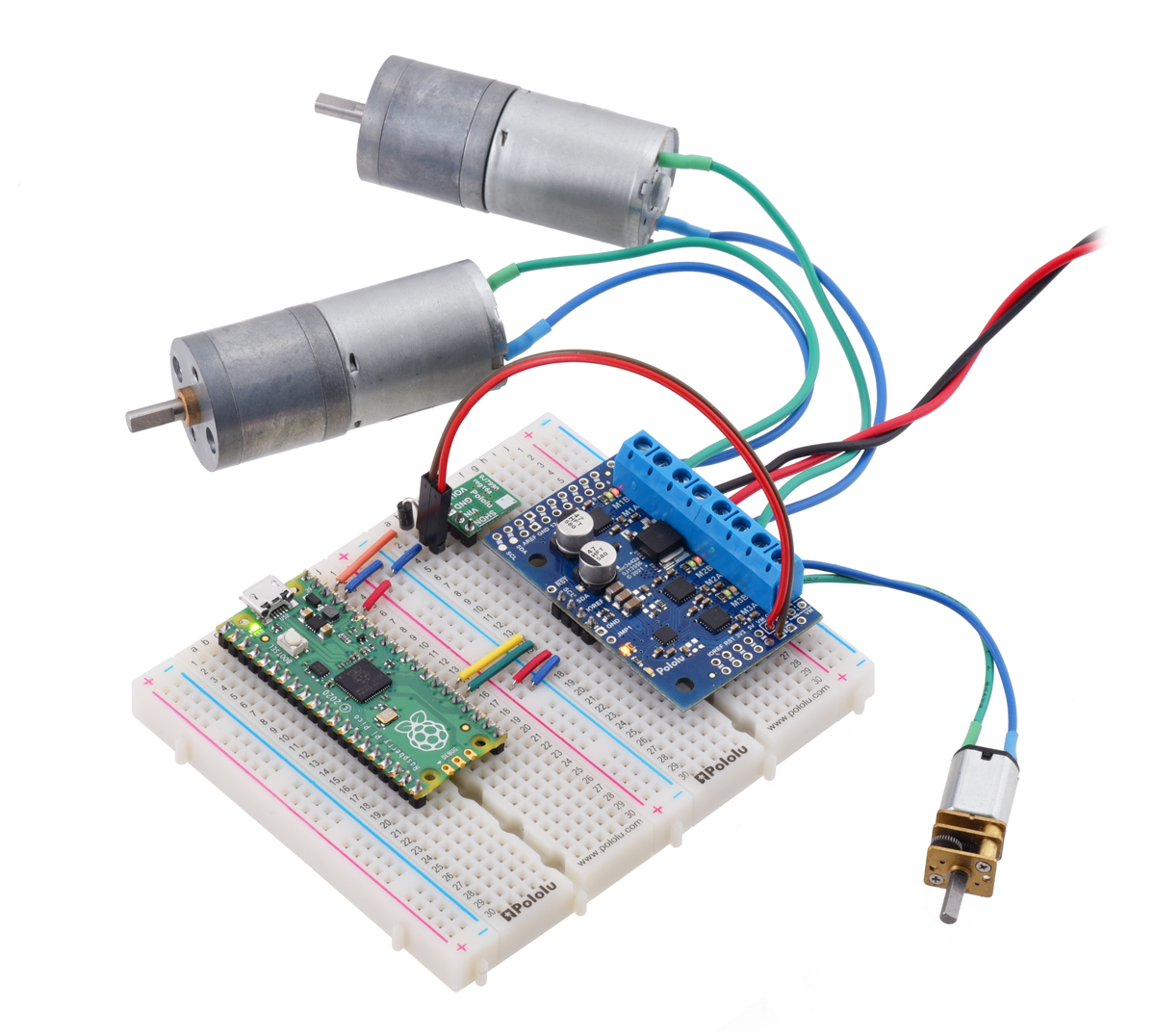 |
A Raspberry Pi Pico on a breadboard using a Motoron M3S256 shield to control three motors. |
|---|
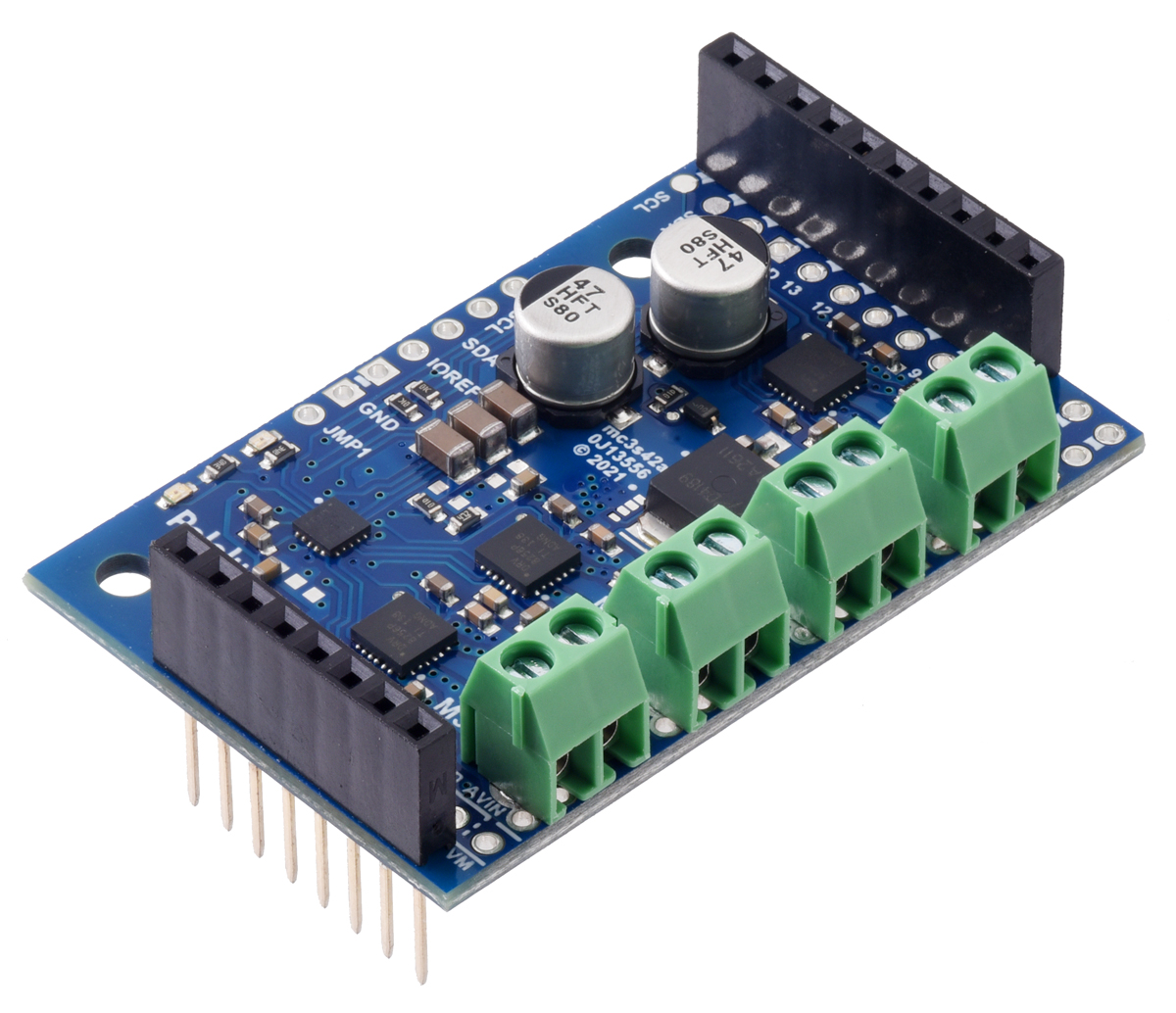
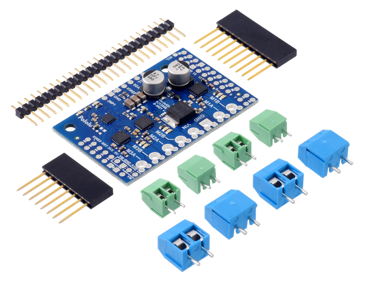
The Motoron M3S256 is available in three versions with different connector options:
- soldered with stackable headers and terminal blocks
- as a kit with connectors included but not soldered
- as a board only with no connectors included
|
|
|

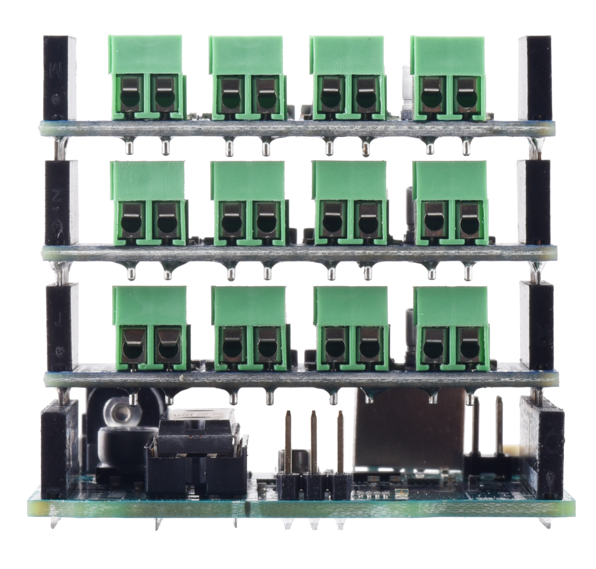
You might wonder why the assembled version comes with 3.5mm-pitch terminal blocks soldered in when the through-holes are spaced 5 mm apart. The answer is that the smaller 3.5 mm terminal blocks allow for more clearance when the shields are stacked, reducing the risk of shorting them to each other, but we still designed the board with bigger holes and wider spacing for maximum flexibility.
 |
For more information about the Motoron M3S256, see the product pages and the comprehensive user’s guide. We have plans to expand the Motoron family with more versions including Raspberry Pi-compatible form factors and higher-power models, so expect more announcements soon!
Related products


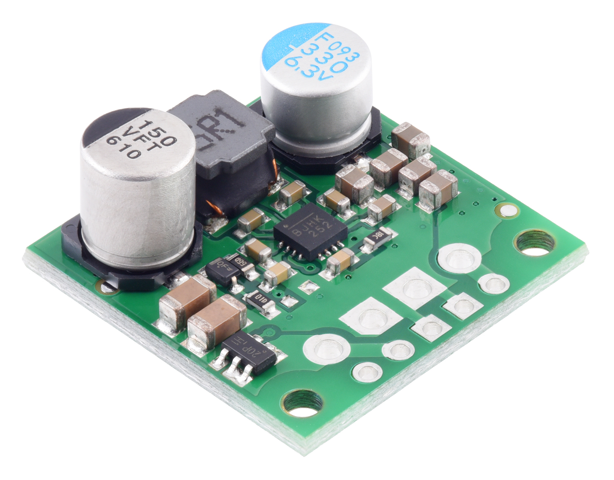
New products: S13VxF5 step-up/step-down voltage regulators
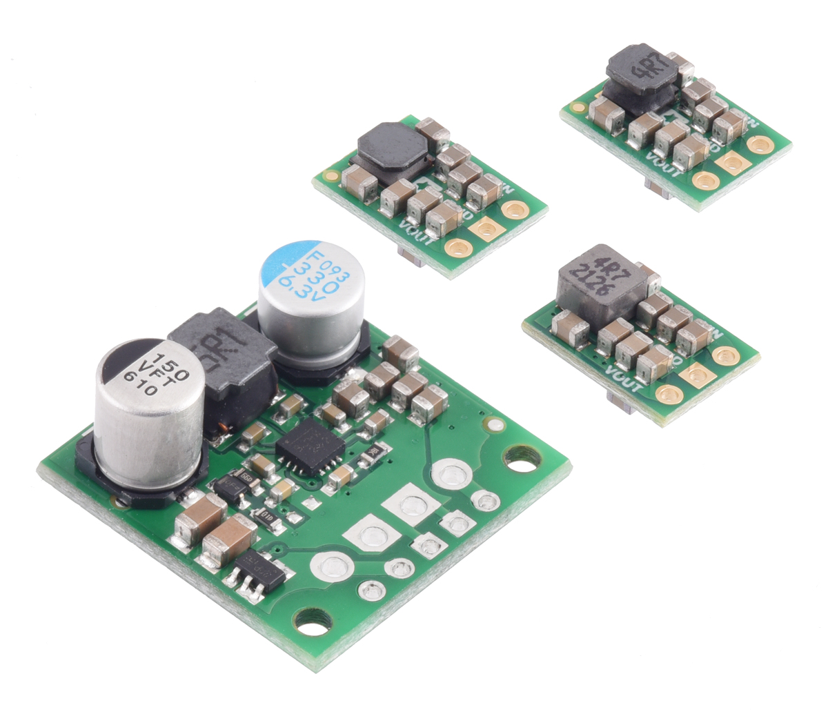 |
We have released three new members of the S13VxF5 regulator family:
- 1A Step-Up/Step-Down Voltage Regulator S13V10F5
- 1.5A Step-Up/Step-Down Voltage Regulator S13V15F5
- 2A Step-Up/Step-Down Voltage Regulator S13V20F5
These lower-current variations are much smaller than the existing 3A Step-Up/Step-Down Voltage Regulator S13V30F5, but they can handle continuous output currents of 1 A, 1.5 A, and 2 A, respectively, with efficiencies from 85% to 95%. Like the S13V30F5, these smaller units accept input voltages from 2.8V to 22V and feature under-voltage lockout, output over-voltage protection, and over-current protection as well as thermal shutdown and soft-start, but they do not have reverse voltage protection or a disable input.
Each member of the S13VxF5 family has a fixed 5V output, and the components are optimized for different current capabilities. With the S13V20F5 in particular, we are offering a variant with a much more expensive inductor to squeeze out the most power we can in the smallest package.
Related products


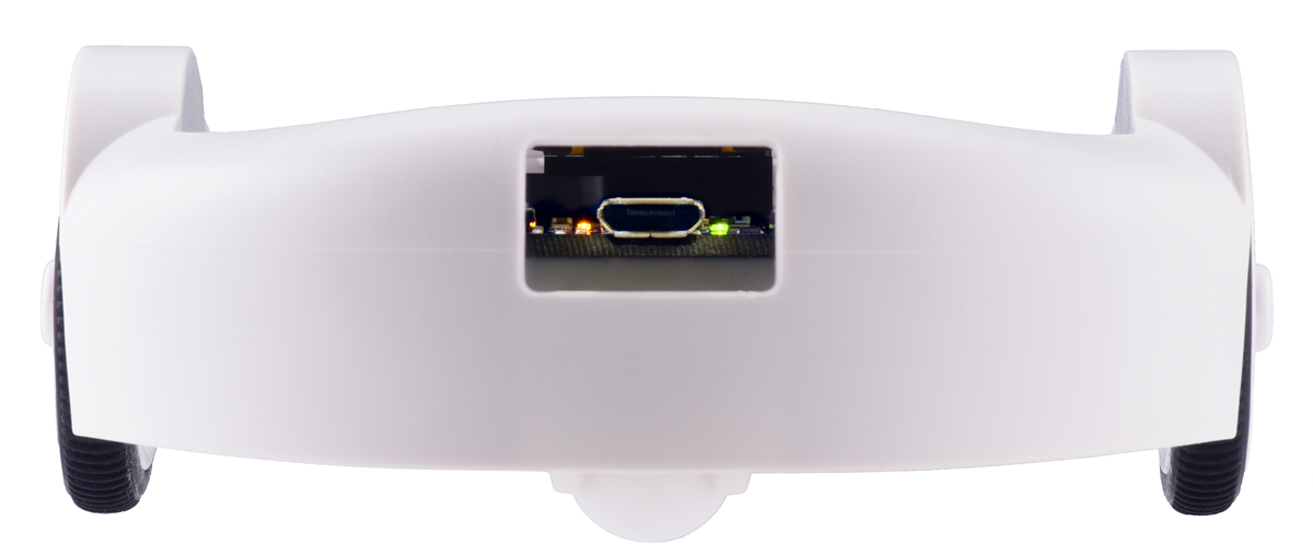
The Zumo gets a graphical display too: new Zumo 32U4 OLED Robot!
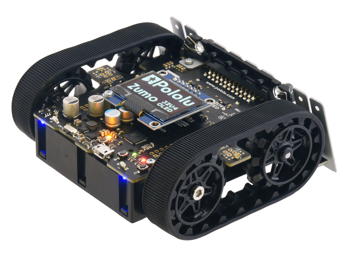 |
Our 3pi+ 32U4 robot got an upgraded OLED display earlier this year, and now it’s the Zumo’s turn with the release of our new Zumo 32U4 OLED Robot!
 |
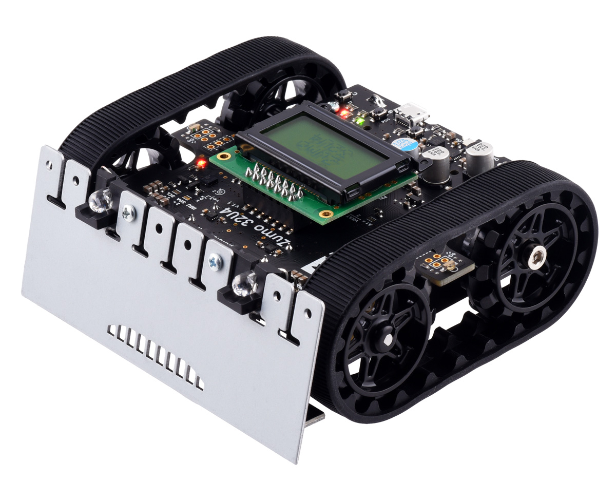
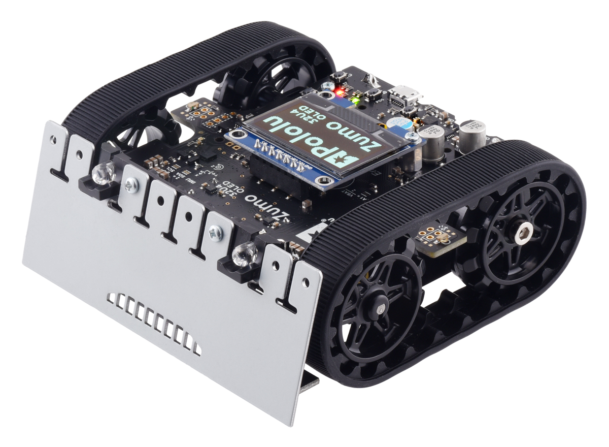
In many ways, this new version is just like the original Zumo 32U4: it’s a versatile tracked robot designed to be a capable Mini-Sumo competitor, but with enough sensors and extra features to enable lots of other applications. The Zumo 32U4 OLED adds to that versatility by replacing the original LCD (liquid crystal display) with a high-contrast graphical OLED display. With this monochrome 128×64 screen, you can present high-density data displays to help you analyze the Zumo’s status and sensor readings, or you can add some flair to your Zumo by showing eye-catching graphics.
We’ve updated our Arduino library for the Zumo 32U4 to add OLED display support as well as an LCD compatibility layer (the same way we did for the 3pi+), letting you easily convert existing programs to run on the OLED version or write new programs that will work on both old and new robots.
As with the LCD version, the new Zumo 32U4 OLED robot is available as a kit (with motors not included so you can select your own to customize performance) or as a fully assembled robot with your choice of 50:1, 75:1, or 100:1 motor options
|
|
Related products


New products: DRV8256E/P motor driver carriers
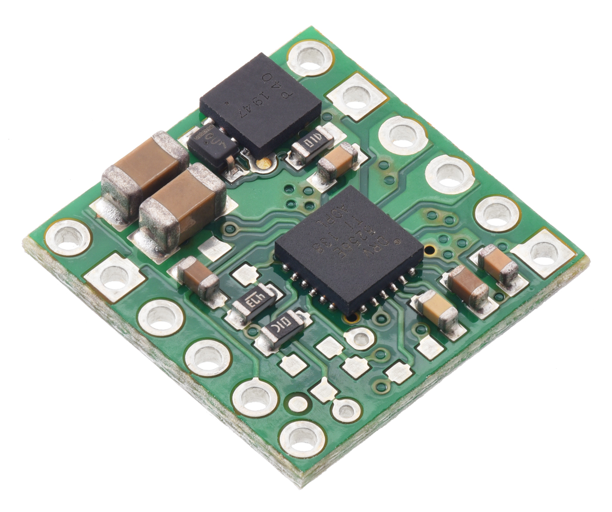 |
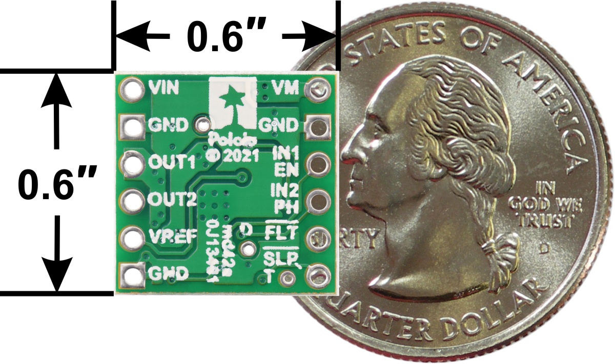
We’re pleased to announce our inaugural products based on the DRV8256E and DRV8256P motor drivers from Texas Instruments, which we are especially excited about. These little carrier boards can deliver a continuous 1.9 A to a single brushed DC motor at voltages from 4.5 V to 48 V, so they have some of the broadest operating ranges of any of our drivers, and they can handle short bursts of considerably higher current (up to 6.4 A for less than a second). They also feature configurable active current limiting, which can help make them good choices for a motor that might only draw around an amp when running but much more when starting.
|
|
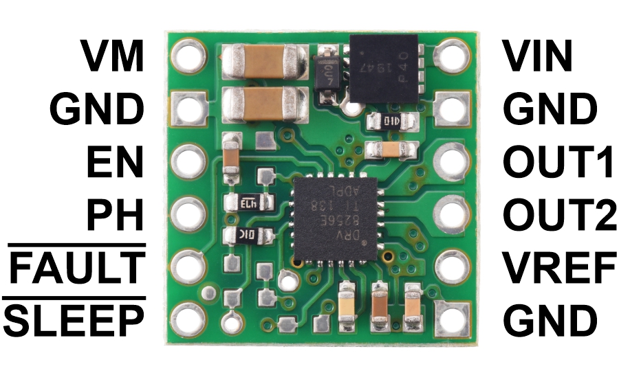
The DRV8256E and DRV8256P are very similar, and we use the same printed circuit board for both chips, but their control interfaces are different. The E version provides a phase/enable interface that lets you control a motor with a single PWM speed signal along with a simple digital direction signal, while the P version provides an IN/IN interface that gives you direct control over the motor outputs but requires two PWM signals for bidirectional speed control.
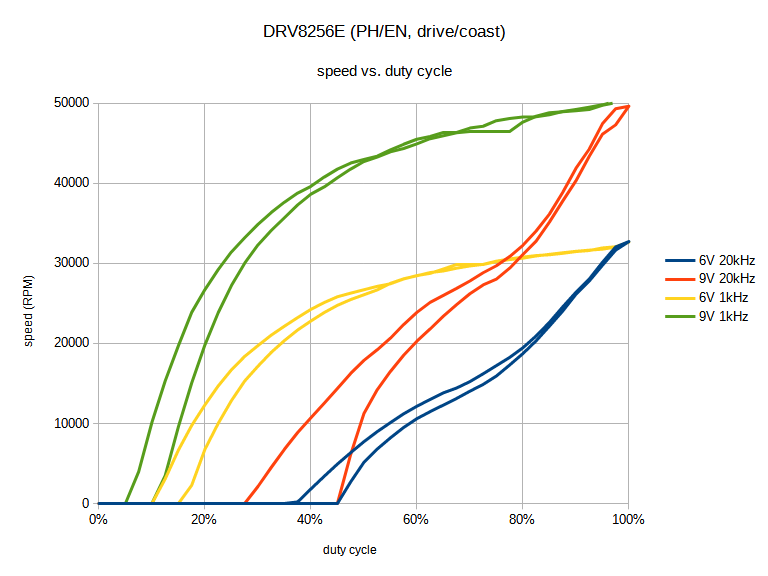
However, there is also a tradeoff with these two ICs. The DRV8256P uses drive/brake operation, shorting the motor outputs together and electrically braking the motor during the off portion. Many other TI drivers with phase/enable interfaces (like the DRV8838) also use drive/brake, but the DRV8256E does not: it operates in drive/coast mode, where the motor outputs are high impedance during the off portion of the PWM cycle, allowing the motors to coast. We don’t know why TI made a different decision for the DRV8256E, but it seems likely they have some high-volume customers who prefer it this way.
In our experience, drive/brake mode provides a much more linear relationship between PWM duty cycle and motor speed, so for an application where that is important, you might choose to accept the need for an additional PWM signal to get that improved linearity. These graphs show the difference in one specific scenario (powering a high-power micro metal gearmotor with no load):
|
|
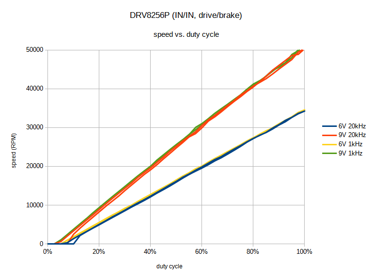
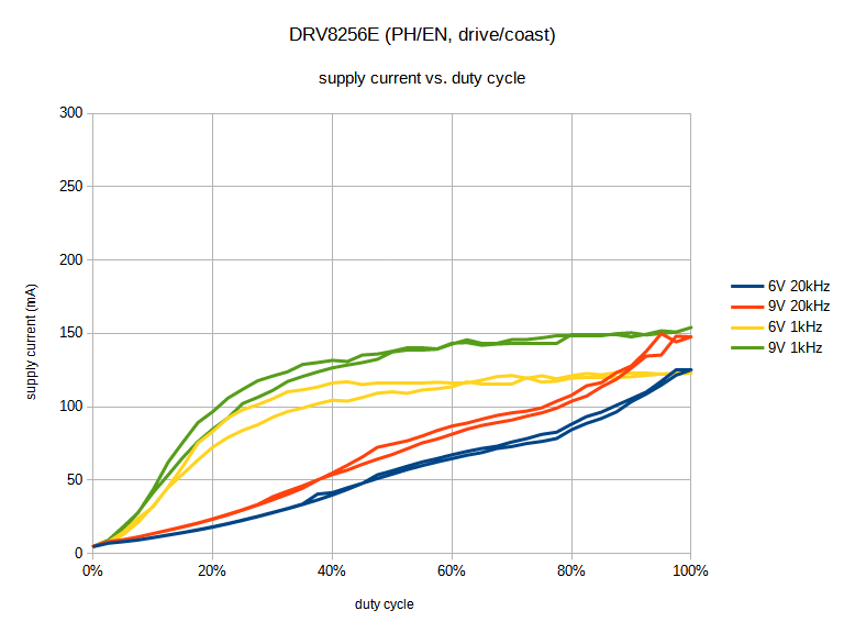
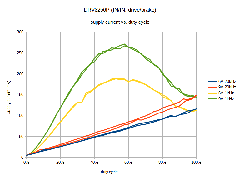
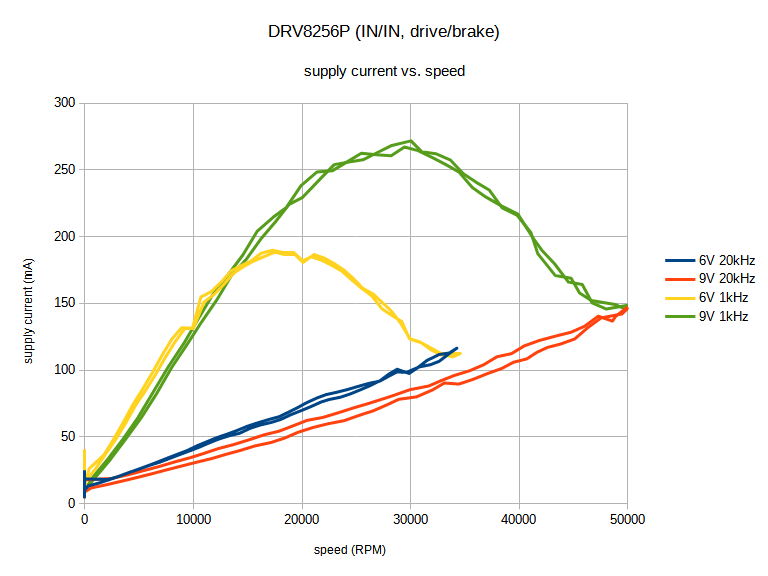
However, graphing the relationship between duty cycle and the current drawn by the motor driver from the supply reveals some more interesting differences. Specifically, at lower PWM frequencies, drive/brake operation uses much more current at intermediate duty cycles as the motor current ramps up and down for each PWM cycle:
|
|
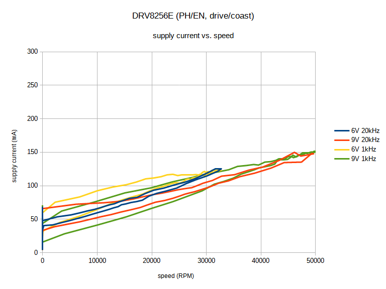
Finally, graphing current draw against motor speed shows that drive/coast can be more efficient for a given speed compared to drive/brake. So for an application with closed-loop speed control where it’s not as important for duty cycle to correspond linearly with speed, using drive/coast might be preferable if the PWM frequency is low.
|
|
If you have any thoughts about drive/brake vs. drive/coast and their use in different applications, we would be interested in hearing about it.
For more information about these drivers, see their product pages:
Related products


New 3pi+ 32U4 OLED Robot with graphical display!
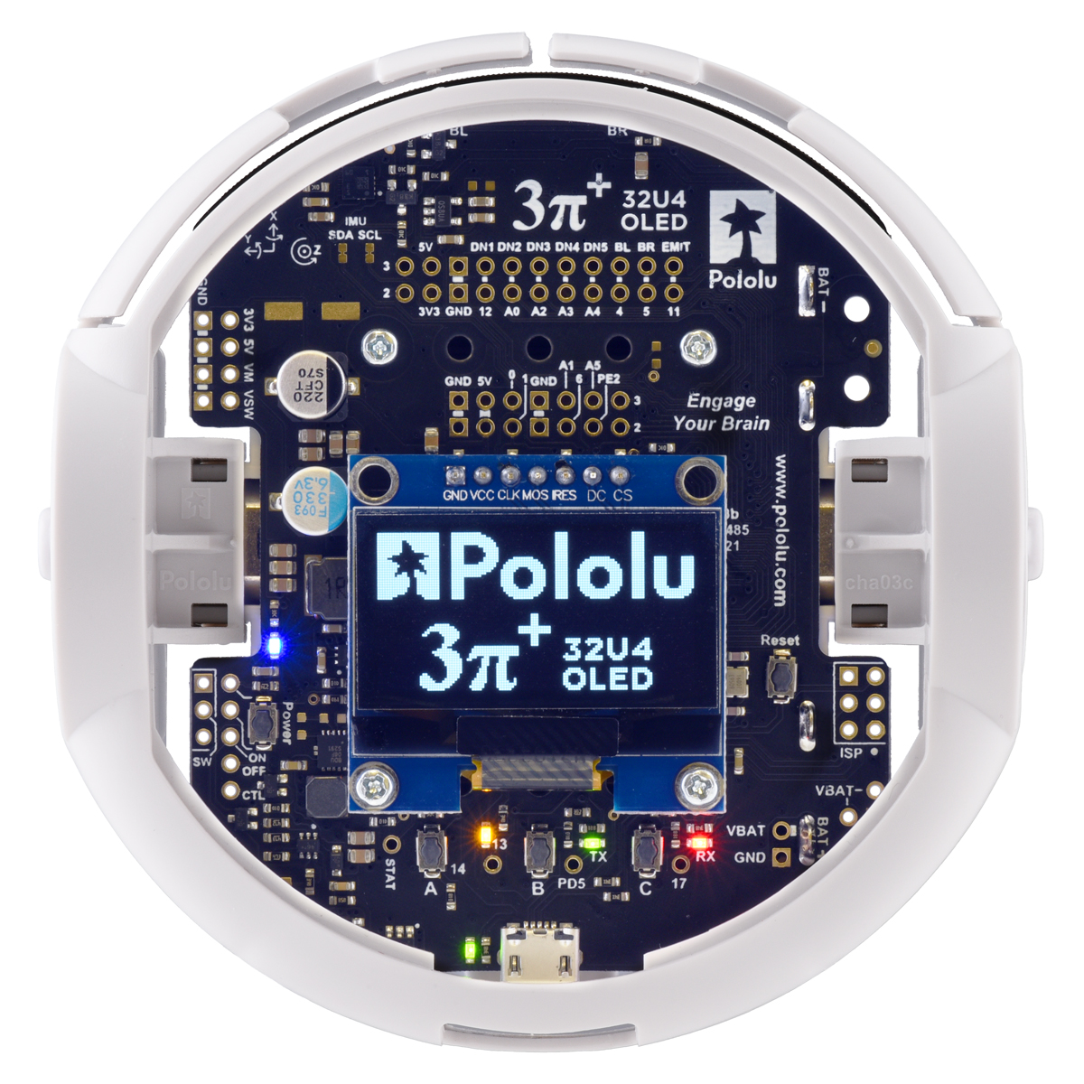 |
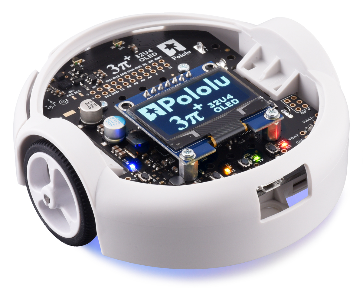
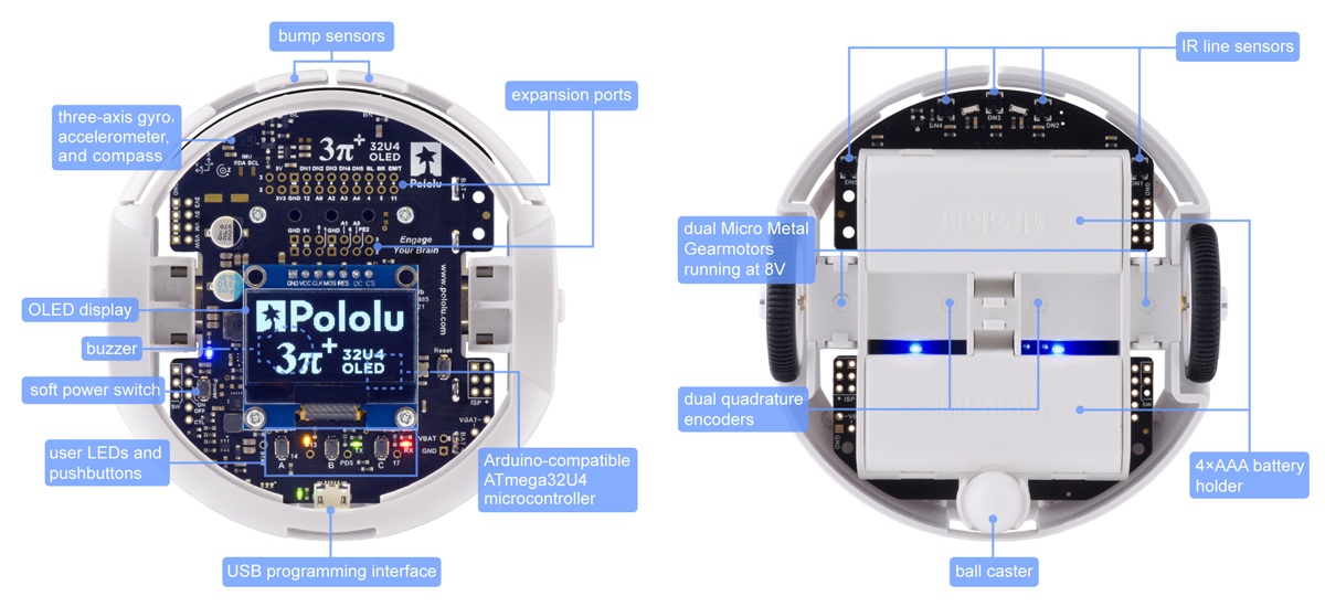
We are very excited to announce that the 3pi+ 32U4 OLED Robot is now available! This is an updated version of the original 3pi+ 32U4 Robot that replaces the old LCD with a monochrome 128×64 OLED display, giving it the ability to display fancy high-contrast graphics while following a line course, navigating a maze, or doing whatever it is that you want this compact but versatile mobile platform to do.
|
|
For more than 16 years, starting with some of our oldest products (from well before I joined Pololu), we have used HD44780-compatible alphanumeric liquid crystal displays on our robots and robot controllers. These LCDs have been around forever and are limited to displaying simple text on a fixed grid, but they are also ubiquitous: there are plenty of manufacturers still making displays that use the standard HD44780 interface.
 |
Pololu Orangutan Robot Controller connected to an AVR ISP (serial version). |
|---|
It’s unlikely that we would have much difficulty sourcing this kind of display any time soon (as long as the pandemic doesn’t mess things up too badly), so using them in our products has always been a safe option despite their graphical limitations. The original 3pi+ 32U4 that we released late last year was our most recent design to include LCD support.
Meanwhile, monochrome organic light-emitting diode (OLED) displays have become increasingly popular in electronics over the last decade or so, and it’s not hard to see why: you can draw graphics on them, they can fit more information on the screen, they’re easier to read in the dark, and they just plain look cooler. But even though you might be able to go to eBay or Amazon and order a cheap OLED display for your project when you want one, it’s critical that we find a dependable supplier for a component like this before we can start to design it into our products.
That is why the availability of the 1.3″ OLED module we announced recently was actually a pretty big deal for us: it means that we finally have a source that we can rely on for larger quantities of these displays. The 3pi+ 32U4 OLED is the first of what we hope will be many robots and control boards that make use of the graphical capabilities offered by an OLED screen.
 |
Like the original 3pi+ 32U4, the newer OLED version is available with three different motor options, either fully assembled or as a kit:
| 3pi+ 32U4 OLED Version | Products | Micro Metal Gearmotor | Top Speed | Comments |
|---|---|---|---|---|
| Standard Edition | assembled or kit | 30:1 MP 6V | 1.5 m/s | good combination of speed and controllability |
| Turtle Edition | assembled or kit | 75:1 LP 6V | 0.4 m/s | longest battery life, easiest to control, good for swarm robots or introductory robotics courses |
| Hyper Edition | assembled or kit | 15:1 HPCB 6V | ~4 m/s | very fast and difficult to control, easy to damage; only recommended for advanced users |
For anyone who wants to use different motors than the options above, the 3pi+ 32U4 OLED control board is likewise available separately and can be combined with a 3pi+ chassis and a pair of motors to build a custom robot.
We will be phasing out the original 3pi+ 32U4 robots and kits (they will remain available by special order), but that does not mean the old versions are suddenly obsolete or that you will have to learn an entirely new platform to use the new OLED version. Aside from the display interface, the hardware on the LCD and OLED versions is exactly the same, with features including encoders, line sensors, front bump sensors, and a full IMU (inertial measurement unit).
From a software perspective, it can actually be pretty challenging to work with graphics, especially on a small processor like the ATmega32U4. The simplicity of a text LCD can be an advantage in that you can essentially just ask it to do something like printing the letter “A” on the first column of the second row. On a graphical display, even if you just want to show some text, you have to define the shape of the letter in pixels; optionally composite that shape into a memory buffer; and then send the complete pixel data to the display. That means you have a lot more control over how that letter “A” is shown, but it takes a lot more work to do it.
To help get you started, we’ve developed an LCD compatibility layer as part of our Arduino library for the 3pi+ 32U4. This makes it easier to use the OLED screen for common display tasks, and it’s straightforward to write programs that will work on either version of the robot with minimal changes, since you can update an existing program to run on the OLED version by changing just a single line of code.
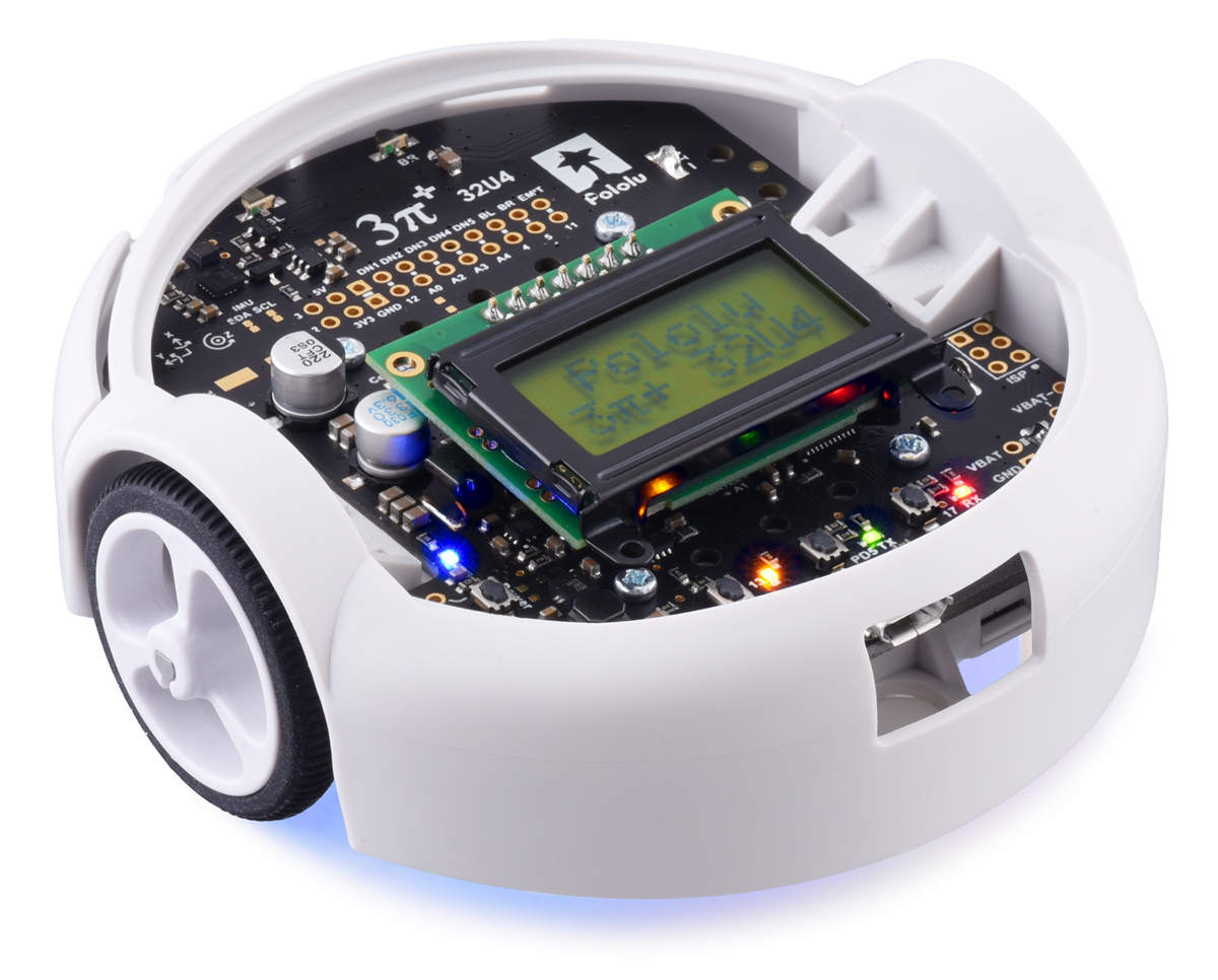
 |
A 3pi+ 32U4 OLED and an original 3pi+ 32U4 running nearly identical programs and displaying the same text. |
|---|
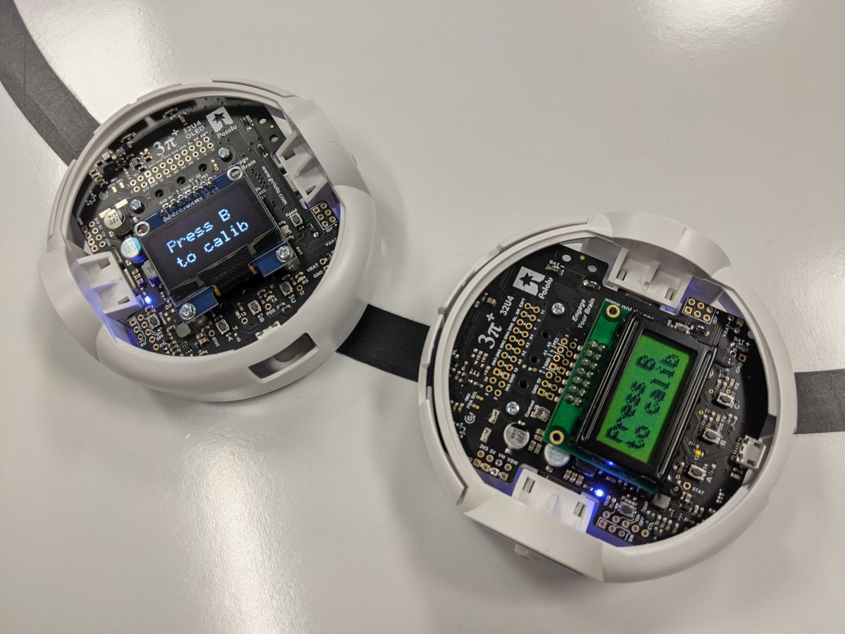
Additionally, the same library makes it trivial to get the benefit of a higher-density text area: you can easily “upgrade” from an 8×2 character grid to an 11×4 or 21×8 layout.
 |
Higher-density text layouts on the displays of some 3pi+32U4 OLED robots. |
|---|
We plan to continue improving our libraries to give you more options for efficiently working with both text and graphics on an OLED display; stay tuned for updates!
|
|
|

Related products


New product: 1.3" graphical OLED display
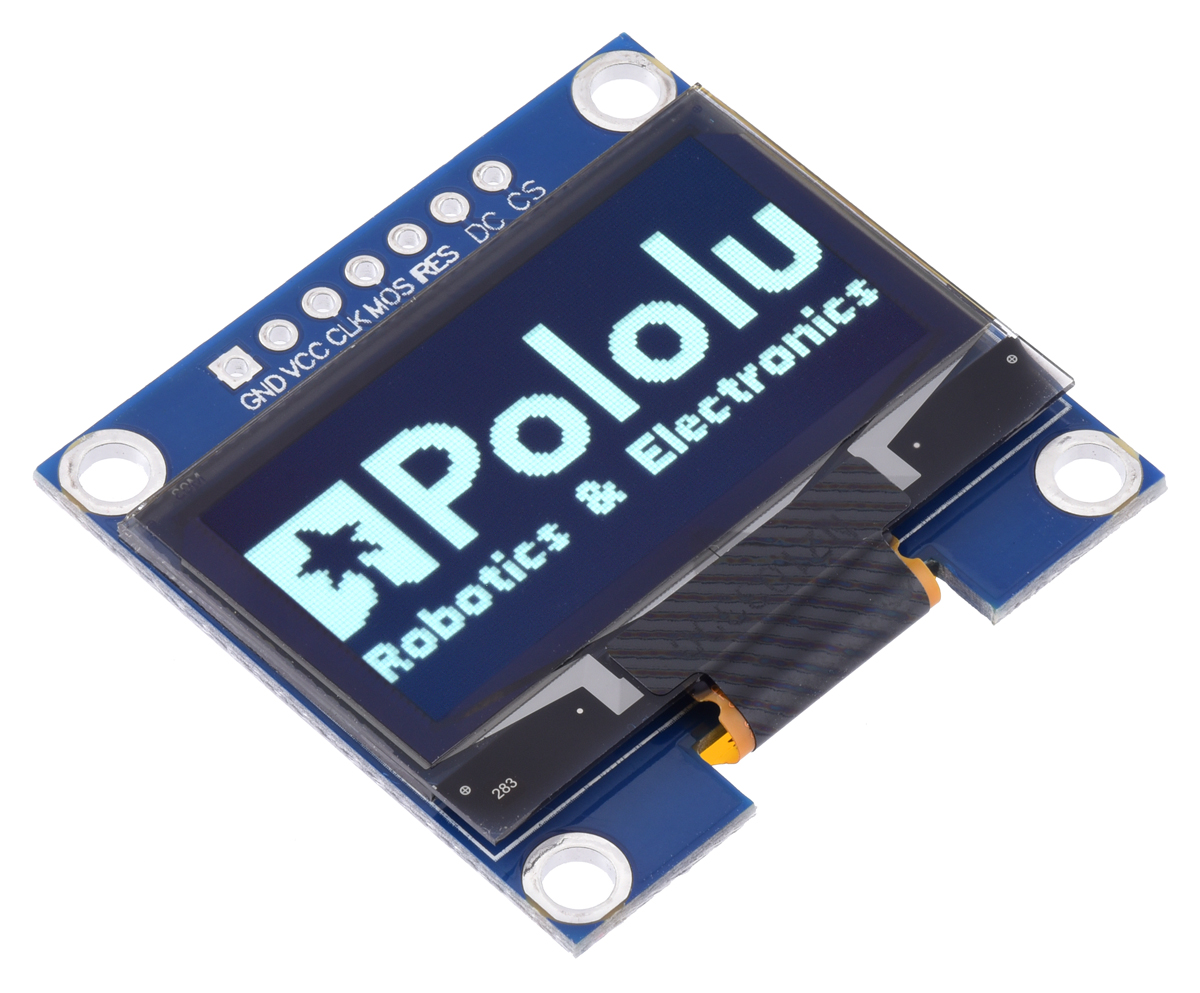 |
We’re now selling an OLED display module that you can use to add some fancy graphics to your project! This monochrome OLED screen measures 1.3 inches diagonally and uses a common SH1106 driver that can be controlled via SPI communication. (For more information, see its product page.)
 |
Graphical OLED Display: 128×64, 1.3", White Pixels, SPI, Blue PCB, controlled by an A-Star 328PB Micro running at 3.3V. |
|---|
With a 128×64 grid of individually-controllable, high-contrast pixels, this OLED display can show a lot more information (and looks a lot cooler) than simple text-only LCD screens. We’re working on something that can take advantage of these enhanced graphical capabilities, so keep an eye out for updates!
Related products

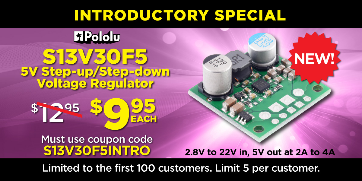
New product: 5V Step-Up/Step-Down Voltage Regulator S13V30F5
 |
I started routing the PCB for the S13V30F5 5V step-up/step-down voltage regulator in January of 2020, and we were in the middle of testing the assembled prototypes when the pandemic shutdowns hit. Like lots of other things in 2020, the project got put on hold because appropriate testing requires a decent amount of equipment and is not the easiest thing to do remotely. That only makes it more exciting to announce that the S13V30F5, our most powerful step-up/step-down regulator, is now available! It operates from 2.8 V to 22 V and steps that voltage up or down as necessary to produce a fixed 5V output with typical efficiencies of 85% to 95%. As shown in the graph below, it can deliver around 3A continuously when the input is near 5V.
 |
This new regulator measures just 0.9″ × 0.9″. That is almost half the size of our previously highest-power step-up/step-down units, the S18V20Fx family, which we have recently started rationing due to impacts from the global semiconductor shortages.
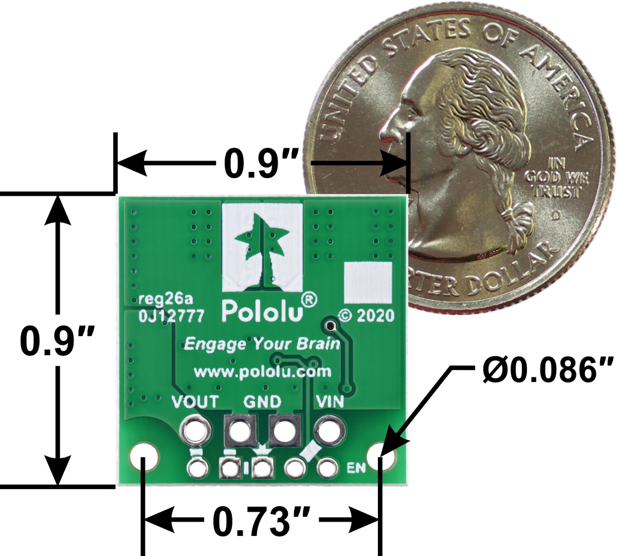 |
5V Step-Up/Step-Down Voltage Regulator S13V30F5, bottom view with dimensions. |
|---|
To help celebrate finally releasing the S13V30F5, we are offering an extra introductory special discount. The first hundred customers to use coupon code S13V30F5INTRO can get up to five units for just $9.95 each!
Related products
New high-speed linear actuators
We are excited to announce the addition of new GF23-series high-speed linear actuators to our already extensive linear actuator selection. This brand new Glideforce series from Concentric International is specifically designed for high-speed, light-duty applications, offering almost twice the speed of our previously fastest options while still supporting almost the same dynamic loads. This video demonstrates the speeds of the four types of light-duty actuators we carry:
They are available in 2″, 4″, 6″, 8″, 10″, and 12″ lengths with or without a feedback potentiometer. The table below shows how these new units compare to our other light-duty options, which are slower but stronger:
This brings our total selection of light-duty actuators to 48 options, and our total overall selection of linear actuators to 82 options, all stocked and available to ship the day you order.


Home | Forum | Blog | Support | Ordering Information | Lists | Distributors | BIG Order Form | About | Contact
© 2001–2025 Pololu Corporation


