Pololu Blog » Posts tagged “community projects” »
Posts tagged “community projects” (Page 2)
You are currently viewing a selection of posts from the Pololu Blog. You can also view all the posts.
Popular tags: community projects new products raspberry pi arduino more…
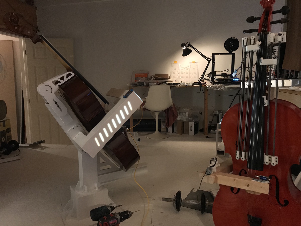
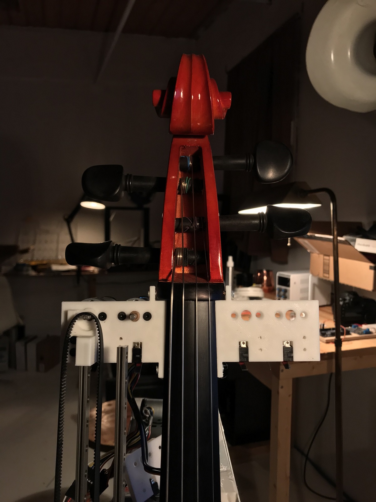
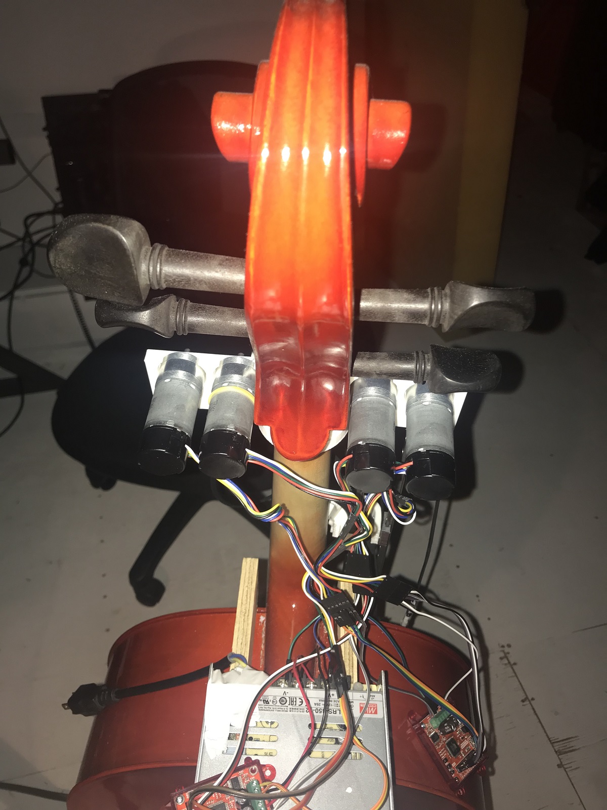
Empty Vessels: a performance of robots, cellos, and artificial intelligence
Artist David Gardener contacted us recently to share his work, Empty Vessels (seen in the above video), an immersive audio visual installation that explores the connection between machines, data, and their environment. The piece features three cellos played by custom built robotic structures that perform music composed in real time. It premiered in November 2019 at the Society for Arts and Technology in Montreal, where it performed for sold out audiences for two weeks! David was kind enough to answer our questions about the piece and allow us to share his answers along with some more footage and pictures with you below:
 |
How long did you work on the piece?
The project started as an idea by myself (David Gardener) and Greg Debicki about a year ago. It remained an idea for most of the year until we were approached by the Society for Arts and Technology in Montreal (SAT) for help funding the project, where we could work on the project as artists in residence. At the end of the residency (in November) we would also premiere the show. This gave the project a very fast timeline taking just two and a half months from concept to presentation for two weeks of shows. I think it is probably the quickest timeline I have ever worked to, having to design, engineer & build the whole project.
Can you tell us which products of ours you used and how they were used in your project?
For the project I used the following components from Pololu:
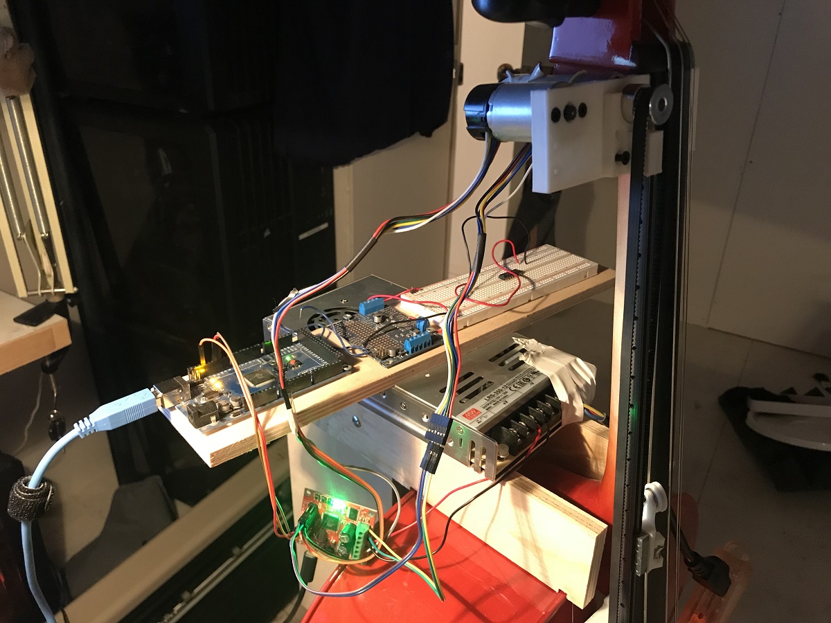
- 12 x 9.7:1 Metal Gearmotor 25Dx63L mm HP 12V with 48 CPR Encoder (one for each string on each cello)
- 6 x RoboClaw 2x7A Motor Controller (two per cello to drive those motors)
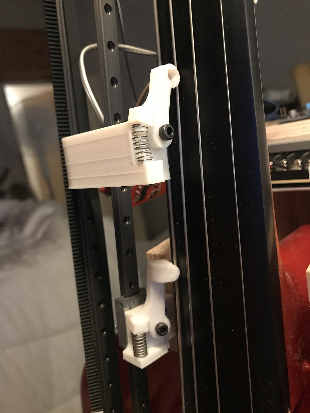
These were used to drive linear slides that moved the note sliders up and down the fingerboard. The reason for using this method was because I am a cellist myself, and the ability to slide between notes is really important in the sound of the cello. Unlike a guitar, there are no frets on a cello’s fingerboard, so the note sliders have to move to very accurate positions on the fingerboard to make sure that the notes are nicely in tune. On startup the motors would all drive the sliders to a home position using a limit switch. From there they would move to the different notes just by driving the motors to pre-defined positions. I decided to use a slider per string on each cello to maximise the amount of notes that could be played simultaneously, meaning they could play 12 note chords, or fast melody lines by splitting the melody across the 3 cellos.
|
|
|
Did you design the slider systems for the fingerboards? It looks like some of the parts might be 3D printed; are the design files available anywhere?
Yes, I designed the whole robotic system from scratch. The cello is such a beautiful instrument in both design and sound. However it is designed specifically for a human body, none of the strings are parallel or in the same plane even, they all diverge towards the bridge. I didn’t want to change the actual instrument in any way for this project. This complicated the build a lot! On top of that, no two instruments are the same, so I had to make sure that the parts could be adjusted in the different planes depending on the instrument they were attached to. Another difficulty is at the top end of the finger board the strings are very close together meaning the sliders all had to be very thin so as not to collide with each other. In the end all these considerations led me to the decision that I would 3D print all the parts. With such a short build timeline, this meant I could design and print revisions of all the parts much quicker than if I was making all the parts by hand in the workshop.
The designs for the parts are not available at the moment as they are very much working prototypes! I plan to upload them for anyone that wants to see them at a stage in the future that I am happy with them.
 |
Can you tell us what your motor control setup is? (What motor drivers are you using, how are you processing the encoders, how are you coordinating all the movement, etc.?)
So I think I answered this in question 2. But a more general overview of the working of the cellos is – The main brain of the three cellos is the software MAX MSP (running on a PC). This would send position data over serial to an Arduino which then told the RoboClaws the next position to send the motors to. The RoboClaws were running in closed loop mode so they were dealing with the encoders directly.
We noticed you have some fans pointed at the upper bank of motors on each cello. Are the motors or controllers overheating, or is that to protect the cellos from getting too warm?
That is funny. Yes, originally I was using your 4.4:1 gear ratio 12 V motors as I really wanted the note sliders to be whizzing up and down the fingerboards like a cello maestro. But after burning out some of the motors by driving them too hard, I decided to switch to the next gear ratio down (and actually even they were getting hot). But by this point I had already locked off the design and ordered all the motors as the opening night for the piece was in three weeks. So to make sure I didn’t lose any more motors, I added some forced air cooling (just a silent fan sat on a bar stool pointed at the motors of each cello)… it added a slight bit of rock ‘n’ roll to the show.
Can you give us some details about how the music is generated?
So the project is headed towards having a fully artificially intelligent score where the music is generated on the spot and then played. The project is designed to also play in a museum environment where it will sit and play for its audience forever evolving music, with the intensity of the compositions controlled by the number of people it is playing to. However, it is currently in a more generative state where it will play music based on a set of musical rules from which it generates the music. This is where my collaborator Greg came into the project, developing patches in MAX MSP that generate the compositions and then work out which string on which cello to send each note to.
Is the piece on exhibit anywhere currently, or are there any planned exhibits coming up?
The piece was shown for a week at the SAT at the end of last year, but it was almost totally sold out so an extra week was added straight after that. The cellos are now back in my studio, where they will be upgraded. They are scheduled for another two weeks of shows at the SAT from March 24th 2020. There are some other shows in Montreal where it will be shown as part of some electronic music and tech festivals (unannounced as of right now). It is then planned for a European tour late summer 2020. It is best to keep track of the dates from my Instagram, @montreal_life_support.
Do you have a website or any social media channels where people can follow your work?
Instagram is probably the best. These are the handles:
- David Gardener: @montreal_life_support
- Greg Debicki: @woulg
Other than that I will be releasing a making-of style video documenting the build in the coming weeks on the YouTube channel.
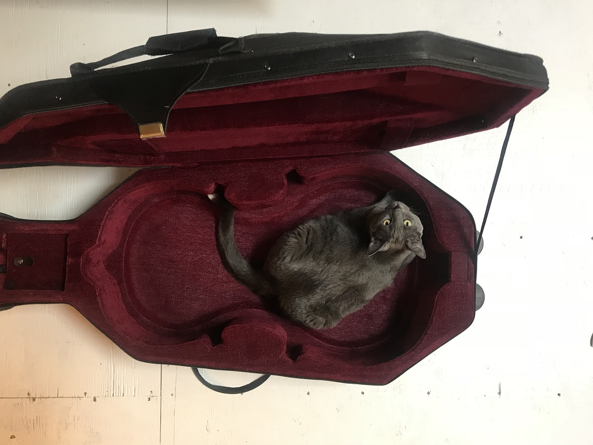 |
Cat tax! |
|---|
Thanks so much to David for sharing your work with us and answering all our questions. For readers in the Montreal area near the end of March/beginning of April, visit the Society for Arts and Technology’s website for showtime and ticket information.
Related products


Ham radio antenna rotor control using a Tic Stepper Motor Controller
Pablo Lewin wanted a way to adjust the antenna for his Ham radio remotely, but was told his antenna controller was too old to upgrade for remote operation. That didn’t deter him though! He got creative and came up with a solution by connecting a stepper motor to his antenna controller and then using one of our Tic Stepper Motor Controllers. Now he can access the computer the Tic is connected to remotely and control the antenna’s position through the Tic’s software. Check out the video below to see his setup:
Here’s the video Pablo recommends at the beginning of his explanation to get up and running with your own Tic Stepper Motor Controller:
Related products


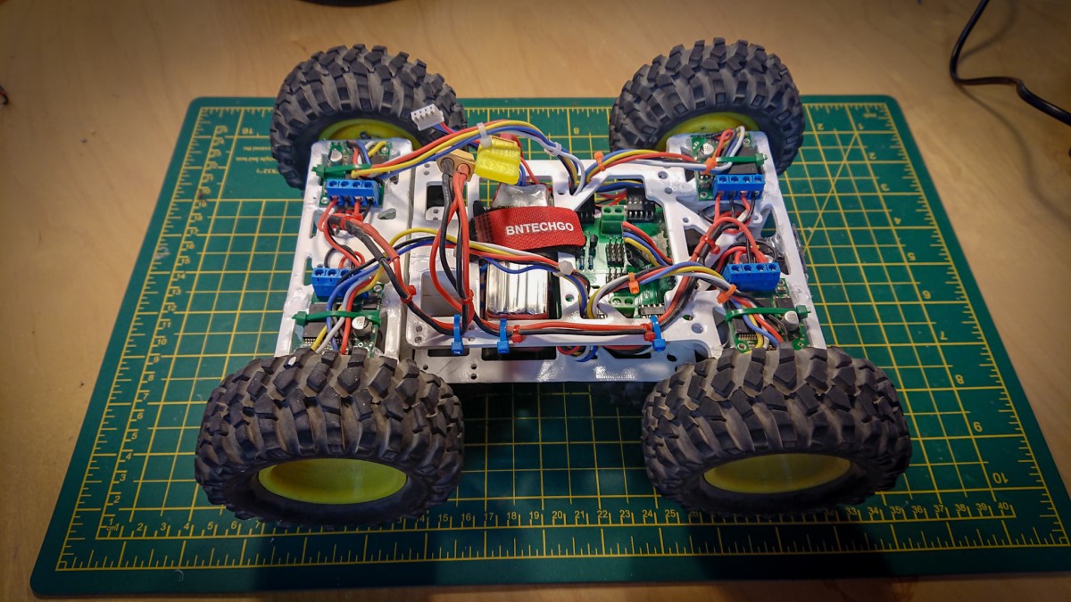
Tito-Stretch: a Pi Wars robot by Hitchin Hackspace
For the second year in a row, Team Hitchin Hackspace and their robot, Tito-Stretch, placed 4th overall in the Pi Wars! They did this at the Advanced/Pro level, which is Pi Wars’ most challenging competition category. (In case you haven’t heard already: Pi Wars is an international robotics competition that focuses on Raspberry Pi-controlled robots.) The video above features Tito-stretch high-tailing it through the obstacle course event. The team’s speedy performance allowed them to climb to the very top of their division, which is a step above their 2nd place finish in 2018’s obstacle course event.
Tito-Stretch is the latest iteration of the hackspace’s competition robot, which has evolved in name and form over the last few years. As we understand it, the team named the original version of their robot Twenty Two Over Seven (22/7 is one way to approximate pi), abbreviated that to TTOS, and then affectionately transitioned to calling the robot “Tito”. Later, the team lengthened their robot and accordingly appended “-Stretch” to the name.
|
|
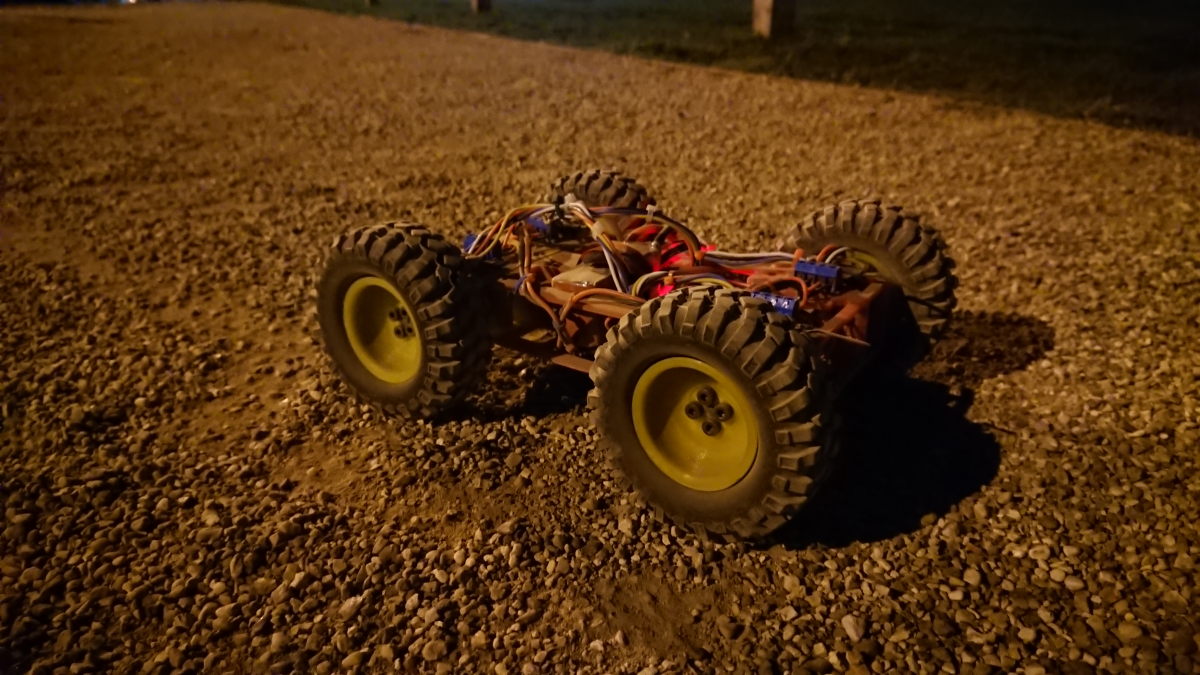 |
Tito-Stretch on gravel. |
|---|
The Tito-Stretch chassis is a 3D-printed design that uses a pair of skateboard bearings in a way that decouples the front and rear parts of the chassis, allowing each part to roll independent of the other. This passive articulation allows the robot to more consistently maintain all four wheels as solid points of contact on uneven terrain. When assembled, the chassis parts clamp down onto four 12V 25D mm gearmotors, and a VNH5019 motor driver controls each motor. A 5V regulator steps down the voltage of a 3S LiPo and powers a Raspberry Pi 3 Model A+, which is the brain of the operation. The team can remotely control their robot with Bluetooth controllers (they currently use a PS4 controller, but have used other devices in the past), and various accessories like a few VL53L0X time of flight distance sensors help enable autonomous navigation. You can find code for Tito-Stretch, and older versions of Hitchin Hackspace’s Pi Wars robots, on their GitHub page.
Great job on your competition this year, Hitchin Hackspace! We hope to hear more about your robots in the future!
Related products


Laser-cut teapot coasters
This past weekend my mom hosted a tea-themed baby shower for me, and after looking around and not finding any party favors I liked, I decided to make my own custom laser-cut teapot-shaped coasters for it. To get started, I searched some free vector file sites for a vector file of a teapot that I liked and could easily prepare for laser-cutting with CorelDRAW. I chose this one designed by Freepik. Once loaded into the software, I resized the teapot and added text. I personally really like cork as a coaster material since it keeps the cup from slipping and absorbs moisture well, so I also picked up some 1/8″ cork place mats from IKEA.
Evidently, cork is not a material we are asked to laser-engrave very often, so I had to do some experimenting with the engraving settings before cutting out prototypes.
|
|

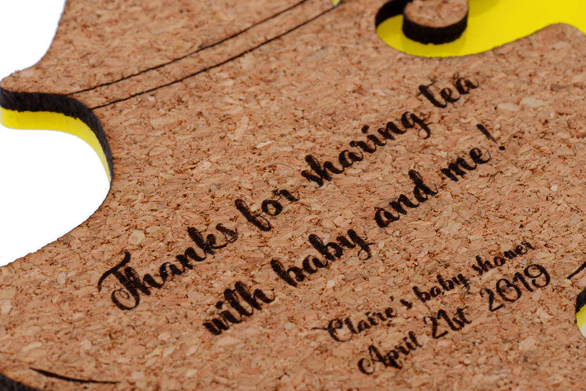
I generally liked the look of the first draft, but realized that at 4 inches total width it was too small to be practical (and readable). In addition, the handle of the teapot was fairly fragile since the cork was only an eighth of an inch thick. Below you can see the first draft of the cork teapot in the upper left. It is missing the small circular embellishment at the base of the handle.
 |
Comparison of different test coaster sizes. |
|---|
For the second draft, I increased the size to about 5.5 inches, edited my file to thicken the areas of the teapot where the handle connects to the base, and started playing with different acrylic backings to make the coasters more durable and colorful. I tried a version with an outline around the cork teapot and one that fit directly beneath the cork.
|
|
|


In the end, I went with the sleeker acrylic with no outline, though most of the others I consulted here preferred the mirrored outline shown on the left above (despite my insistence that it looked like a magic lamp). I cut out a variety of colors and glued them to the back of the cork with rubber cement.
|
|
|


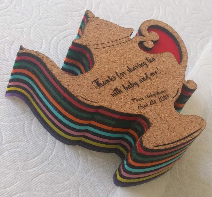
All in all I think they came out well (though I could have made the attachment for the small circle at the bottom of the handle even thicker), and they were definitely a big hit at the party!
If you want to try your own laser cutting project, submit a quote request here!
Related products

Kinetic art installation using 24 Maestros to control 576 servos
 |
This wall-mounted kinetic art installation by Alain Haerri redirects light from 576 independently actuated square panels. A flattened segment of an aluminum can, cut to the same square shape as the panel, decorates each actuator, and a small servo allows the decorated panel to pivot up or down. The servo’s positioning of the panel can alter how much light is reflected, effectively making that individual panel appear lighter or darker. Taken together, the array of panels produces an image with enough resolution and speed for delightful and mesmerizing visuals.
At the heart of the operation is an Arduino Mega, which, with the help of our Maestro Arduino library, communicates with 24 Mini Maestros (with 24 channels each) to orchestrate the movement of servos. The Mini Maestros are wired together and connected to a single software serial port on the Mega, which controls all the Maestros using the Pololu protocol at 200 kilobaud. Additionally, the installation has a built-in camera, which allows it to do things like mirror the movement of people standing in front of it, as this video shows:
You can find a write-up of Alain’s project on the Arduino Project Hub, where he also shares his code, a complete parts list, and a couple more videos of the table in motion.


Video of Caesar, the first-place rover of the 2019 Indian Rover Challenge
The first-place winner of the 2019 Indian Rover Challenge, Team Anveshak from IIT Madras, sent us a link that shows their rover in action! The video is their submission to the 2019 University Rover Challenge (URC) System Acceptance Review (SAR), which is a major qualification round for participating in the URC finals. Good luck with SAR qualifications, Team Anveshak!
We first blogged about Team Anveshak’s rover back in January. For more information on the rover and the competition, including pictures, check out that post!
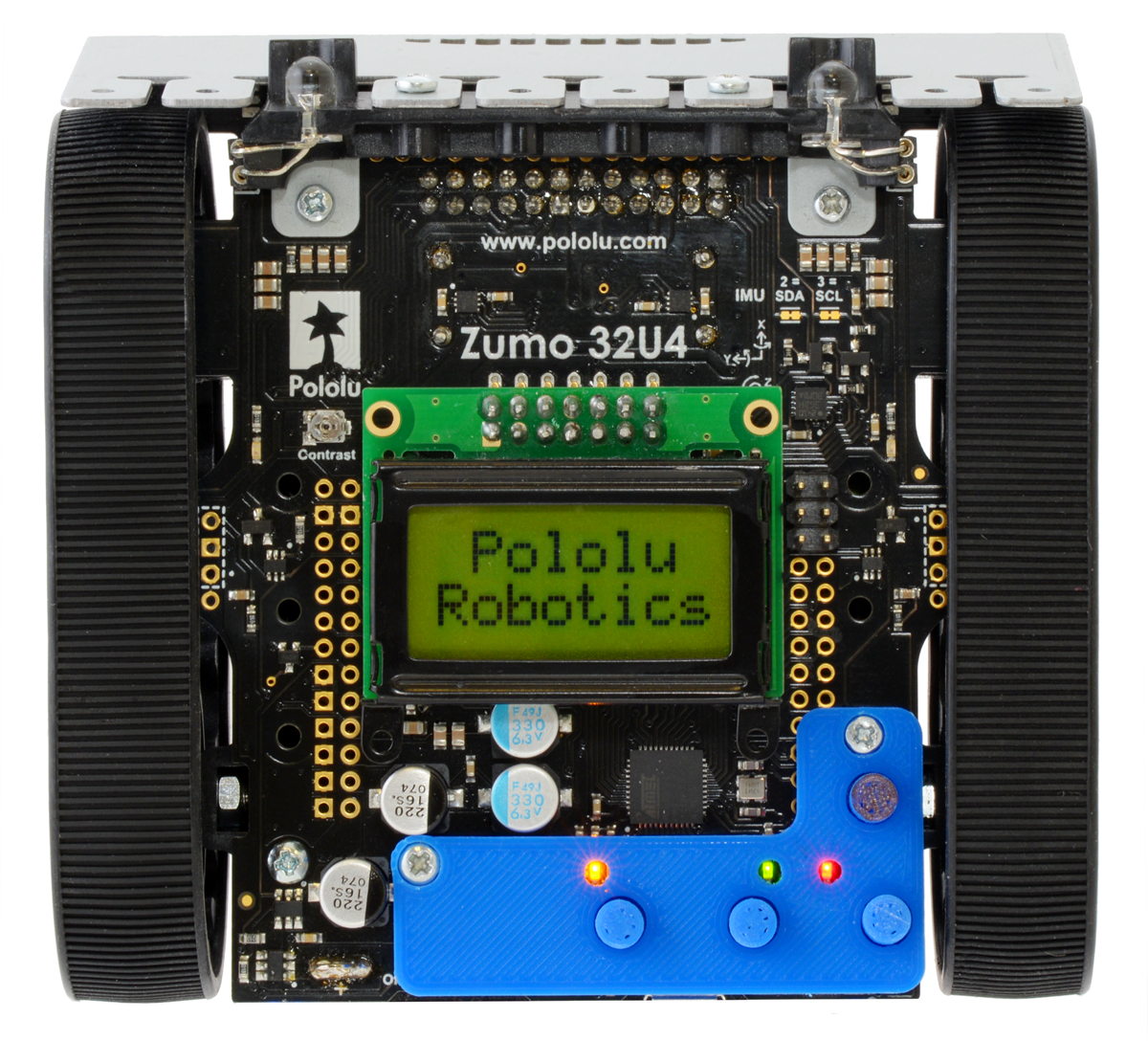
Bigger 3D printed buttons for the Zumo 32U4
 |
Mount Holyoke College professor Peter Klemperer designed a custom add-on for the Zumo 32U4 to give easier access to the user pushbuttons. Peter made the bigger buttons as a response to some of the students in his classes finding it difficult to use the small onboard pushbuttons.
The design even has small cutouts so you can still see the indicator LEDs. To add the adapter plate to the Zumo chassis, you can use two #2 screws and nuts (7/16 inch length screws worked great for me). The easy-to-print STL files along with the Fusion 360 files are available on Peter’s GitHub repository for the project, and you can find more information on Peter’s blog post on his website.
If you print your own bigger buttons for your Zumo 32U4 be sure to let him (and us!) know; we would love to see some pictures! Here’s a shot of the one I printed out for my personal Zumo 32U4:
 |
Related products


Macro photography using Tic stepper motor controllers
|
|
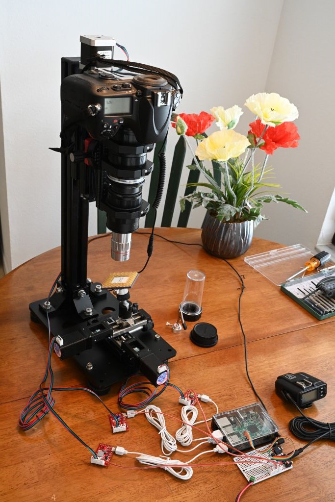
Forum member Mike is using our Tic stepper motor controllers in his automated stack & stitch image acquisition systems, which he has been using to get extremely high resolution images of various integrated circuits. Each system uses linear rails and stepper motors to properly align the camera/lens and the object to be photographed. Two stepper motors position the subject and a third adjusts how close the camera is to the subject. A Tic T500 controls each stepper motor and each Tic connects to a USB port on a Raspberry Pi 3B or Raspberry Pi 3B+, which acts as the main computer. Afterward, Mike stacks the images with Zerene Stacker and stitches them together with Photoshop. Some of his image sessions capture as many as 6000 individual images that are used to produce a single 300 megapixel image!
 |
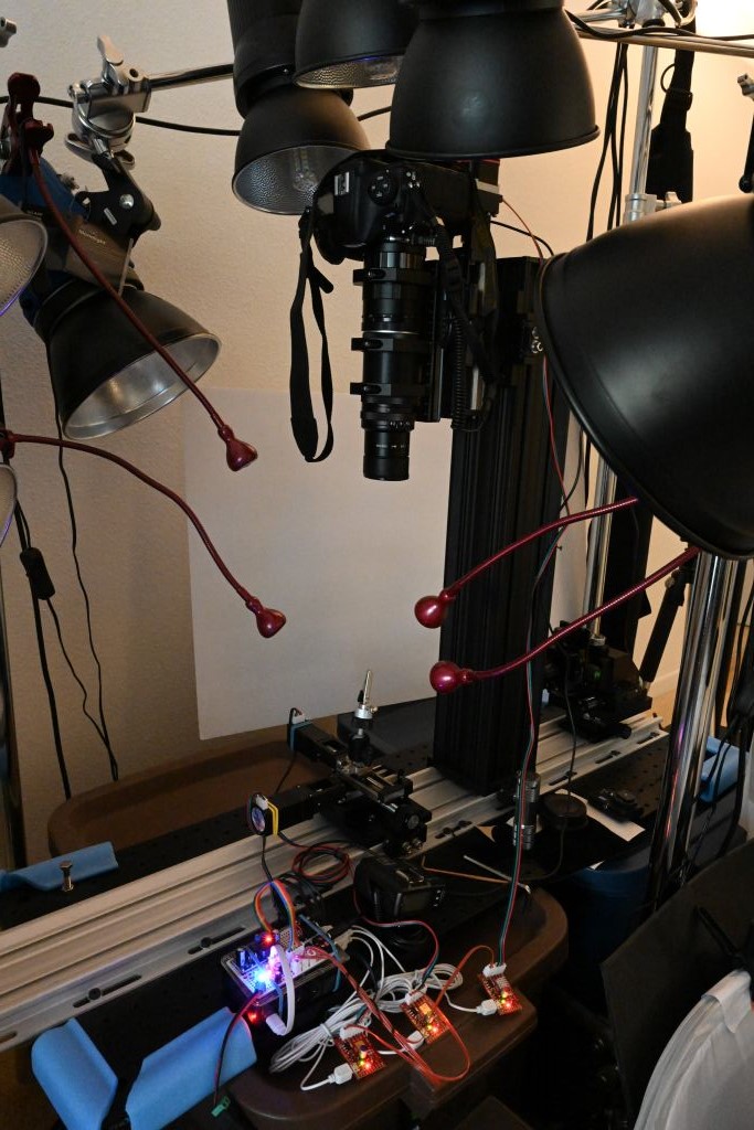
Zooming in on a stack & stitch test image. |
|---|
 |
A close-up view of a stack & stitch test image. |
|---|
You can find more information about Mike’s stack & stitch image acquisition systems (like what specific mechanical hardware he is using) in this forum post. Also, to see and/or download a set of high resolution pictures taken with those setups, follow this link.


Rover team from IIT Madras places first in Indian Rover Challenge
 |
Congratulations to Team Anveshak from IIT Madras, who took first place at the 2019 Indian Rover Challenge! The IRC is a robotics and space exploration-based competition for college students. Participating teams design and build a Martian rover prototype and use that rover to compete in various tasks like obtaining soil samples, operating electrical racks, and picking up and delivering objects.
|
|
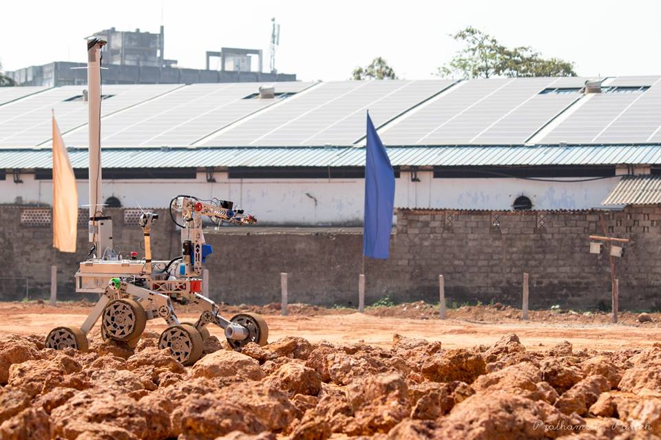
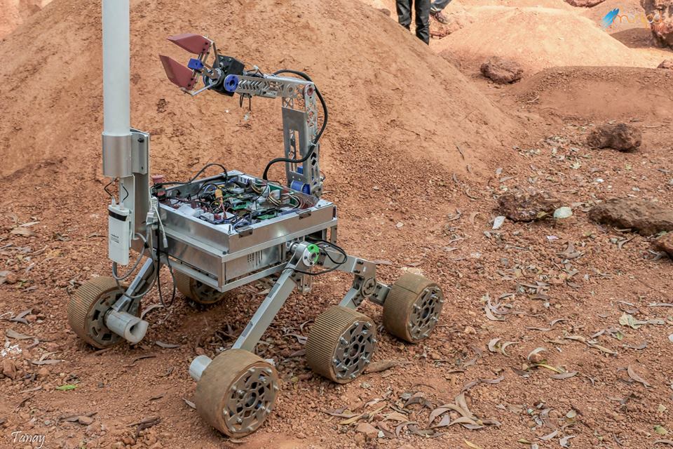
Team Anveshak’s winning rover, Caesar, uses 10 different Pololu products! We are especially excited to hear that their rover prominently features our newer G2 High-Power Motor Driver 24v13 and TB9051FTG motor drivers, using 9 of each of those boards.
We love seeing all the awesome things like this that people are doing with our products! For a more complete list of the Pololu parts used in Caesar, check out the related products listed below. If you want to learn more about the team, check out their website.
8 March 2019 Update: See a video of Caesar in action here.
Related products


Balboa controlled via cell phone over Bluetooth
Drew Wilkerson added a Robotis BT-410 Bluetooth-to-serial board to his Balboa Robot, which allows him to control that Balboa from a cell phone. You can watch the video above to see the Balboa being driven around as it balances. More information about this project, including the code running on Drew’s Balboa, can be found in his post on our forum.
Related products


Home | Forum | Blog | Support | Ordering Information | Lists | Distributors | BIG Order Form | About | Contact
© 2001–2025 Pololu Corporation


