Support » Pololu A-Star 32U4 Robot Controller User’s Guide » 3. A-Star 32U4 Robot Controller with Raspberry Pi Bridge »
3.6. LV regulator
 |
The A-Star 32U4 Robot Controller LV can be powered from a 2.7 V to 11 V external source. The input voltage is regulated to 5 V by a TPS63061 switching step-up/step-down (buck-boost) converter from Texas Instruments; although the regulator itself works with input voltages up to 11.8 V, the motor drivers limit the robot controller’s maximum input voltage to 11 V. (We also make a standalone regulator based on this integrated circuit.)
The regulator’s flexibility in input voltage is especially well-suited for battery-powered applications in which the battery voltage begins above 5 V and drops below 5 V as the battery discharges. Without the typical restriction on the battery voltage staying above 5 V throughout its life, a wider range of battery types can be considered. For example:
- A 4-cell battery holder, which might have a 6 V output with fresh alkalines or a 4.0 V output with partially discharged NiMH cells, can be used to power this A*.
- A disposable 9 V battery powering the board can be discharged to under 3 V instead of cutting out at 6 V, as with typical linear or step-down regulators.
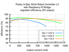
As shown in the left graph below, the LV’s switching regulator has an efficiency – defined as (Power out)/(Power in) – of 80% to 90% for most combinations of input voltage and load.
|
|
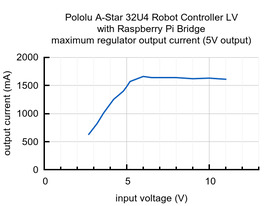
The A-Star’s components, including the microcontroller and LEDs, draw 30 mA to 40 mA in typical applications (without the buzzer). The rest of the regulator’s achievable output current, which depends on input voltage as well as ambient conditions, can be used to power other devices; this can include an attached Raspberry Pi (which typically draws a few hundred milliamps). The right graph above shows output currents at which the voltage regulator’s over-temperature protection typically kicks in after a few seconds. These currents represent the limit of the regulator’s capability and cannot be sustained for long periods; under typical operating conditions, a safe limit for the maximum continuous regulator output current is 60% to 70% of the values shown in the graph.


