Support » Pololu RC Switch User’s Guide » 3. RC Switch with Small Low-Side MOSFET »
3.2. Connecting the RC Switch with Small Low-Side MOSFET
The typical way to connect the Pololu RC Switch with Small Low-Side MOSFET is shown in the diagram below:
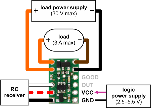 |
Pololu RC Switch with Small Low-Side MOSFET, typical wiring diagram. |
|---|
The RC switch can be plugged directly into an RC receiver or servo controller using a Female-Female servo extension cable. These can be found in our Servo Cables category. The switch will read the signal from the RC receiver, but in the default configuration it will not draw or supply any power to the receiver, so the power wire is optional. The receiver will need its own power source.
Power for the board’s logic needs to be applied to GND and VCC and must be between 2.5 V and 5.5 V. A 5 V regulator would be a good choice for the logic power supply. A 3-cell NiMH battery pack would also work, but a 4-cell NiMH battery pack can be well over 5.5 V when fully charged and would not be suitable.
The negative side of your load supply should connect to the GND pad on the top-right side of the board, and the negative side of the load itself should connect to the LOAD LOW pin. The two pins labeled LOAD HIGH are internally connected and will typically be connected to both the load and the load power supply. There is a flyback (also known as a “freewheeling”) diode between the MOSFET output and LOAD HIGH, which allows you to safely connect an inductive load such as a motor or relay. Alternatively, the positive side of the load could be directly connected to the load supply off of the board. The board’s MOSFET can deliver up to 3 A with VCC at 5 V and can handle load supply voltages up to 30 V.
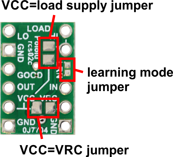
Power jumpers
The setup described above involves three separate power supplies. For some applications, this setup can be simplified by bridging one or both of the power jumpers on the bottom of the board.
 |
Here are some alternative options for powering your system with fewer than three power supplies:
- If the VRC supply from the RC receiver is between 2.5 V and 5.5 V, then you could bridge the VCC=VRC jumper in order to power the board from VRC and avoid the need for a separate logic power supply connected to VCC. Alternatively, supplying power to VCC and bridging VCC=VRC could allow you to power your RC receiver from the RC switch.
- If your load supply is between 2.5 V and 5.5 V, then you could bridge the VCC=load supply jumper, allowing you to power the board from either the LOAD HIGH or VCC pin.
- With both jumpers bridged, the whole system can be powered from a single suitable source.
Large or capacitive loads can cause problems if the same supply is used for the logic (VCC) and the load. In such a configuration, when the MOSFET turns on, VCC might drop below 2.5 V, causing the board to reset. If you try to activate the switch but the board just goes into safe-start mode instead, you might have a power issue, especially if the problem only happens when the load is connected. If you have this problem, you should consider using a separate logic power supply, adding a capacitor between GND and VCC, or using shorter power leads.
Related products


Home | Forum | Blog | Support | Ordering Information | Wish Lists | Distributors | BIG Order Form | About | Contact
© 2001–2024 Pololu Corporation
