This is the third post in a series detailing our experience over the past two years installing and operating a 305 kW array of 630 solar panels on our building in Las Vegas, Nevada. Here are the previous posts:
- Part 1: background starting in late 2022 and how we committed to the $650,000 project by the beginning of January 2023, with a target completion date of May 31, 2023.
- Part 2: installation from January 2023 through first day of operation on October 5, 2023.
I left off with our first look at the SolarEdge monitoring site on October 5, 2023. It’s nice to see nearly real-time generation results and status. The SolarEdge P1101 optimizers (datasheet (334k pdf)) connect to pairs of solar panels, so that is the resolution we can see in the array. Here is a close-up as I write this at 10AM on October 31, 2024, with a section affected by the shadow from an air conditioner circled:
 |
SolarEdge monitoring site solar panel array close-up at 10AM on October 31, 2024. |
|---|
The 1.0.72 pair of panels and 1.0.19 pair of panels at around 130 Wh so far today have generated only about half as much as the nearby panels not affected by the shadows.
Back to the status on the first day a year ago:
Those two black areas represent entire strings that were somehow not communicating with the inverters. But, with the remaining 594 panels producing, we were at around 94% of the total, which generated 1.5 MWh on that first day of monitoring:
 |
First day of SolarEdge-reported results on October 5, 2023, with 594 of 630 panels producing power. |
|---|
The next day, we could see what NV Energy measured. This is the most zoomed-in view available, in 15-minute increments:
 |
October 5, 2023 power meter results in 15-minute increments. |
|---|
The light-blue line is the maximum demand in kW, averaged over 15 minutes, so in this view it has the exact same shape as the bar graphs showing kWh, just scaled up by a factor of 4. Dark blue bars are NV Energy delivering energy to us, green bars are how much energy we put into the grid, and gray bars show periods where power went both ways (better examples of that are coming up). You can see our power consumption start going up as air conditioners kicked in, then go down as the solar contribution covered more and more of our usage, until a little before 9AM, by which point the solar panels were generating more than we were using. By around 4PM, when the SolarEdge graph showed 100 kW production, we crossed back into using more power than we generated.
Zooming out on the NV Energy data lets us see individual day results. I took this screenshot with the cursor on October 5:
 |
Daily power meter results for October 2023 with October 5 totals highlighted. |
|---|
This tells us that NV Energy measured a total of 677 kWh they gave us (the sum of all the little blue bars in the 15-minute graph) and 440 kWh that we gave them (the sum of all the little green bars). The difference of 237 kWh is the net we received, and adding that to the 1,500 kWh SolarEdge reported for the whole day, we consumed 1,737 kWh total, meaning our solar panels covered 86% of our total consumption for the 24-hour period.
As far as I know, this kind of combination of the data from SolarEdge and NV Energy that I just did is the only way I can get the full picture because the NV Energy meter can only measure the combined total of what our facility used and (the negative of) what it generated, and the SolarEdge reports similarly only give a total generated without differentiating what gets used in the building and what goes out to the grid.
This means that I have no way of using the two sets of data to corroborate each other. I expect the NV Energy number to be especially accurate since that is used for billing. For the SolarEdge numbers, I cannot be sure where they are coming from. For example, how close to the final output are they measuring? And even if SolarEdge is really honest and reports the lowest possible number, at the final output from the inverters, there’s no way they could know what losses are in the wires and disconnects between the inverters and NV Energy meter. It’s all probably close enough for the level of analysis I’m doing, and I have no specific knowledge of any errors in the numbers; it’s just always worth keeping in mind whose data we’re using and which direction they might be incentivized to distort things.
Back to the results:
|
Daily power meter results for October 2023 with October 5 totals highlighted. |
|---|
You can see on October 3, the day NV Energy changed out the meter, we had some green, meaning we generated more than we consumed. That’s also the case for most of the weekend days. But besides there being several days with no data that I do not have an explanation for, you can see there’s a lot more dark blue after the first few days. Here’s SolarEdge’s view of the month:
 |
SolarEdge daily solar generation results for October 2023. |
|---|
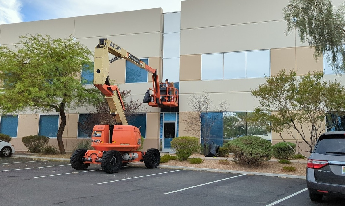
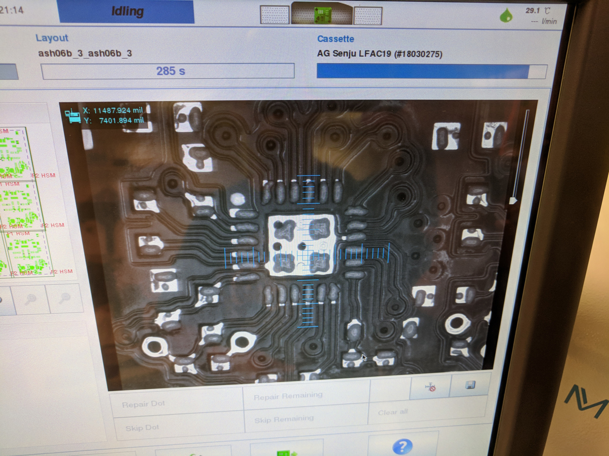
The electricians spent all of October 5 and 6 trying to track down the problem with those 36 panels that were initially not producing. I think some of that time was also spent getting everything entered correctly so that the nice layout display actually matched reality. It’s great when you can just look and see which panels are not producing; it’s not great when those non-producing panels are actually somewhere else on the roof. Even when you can pinpoint the problem down to one string in one section of the roof, that can still be a lot connections to be checking, many of them a lot less conveniently accessible than the ones in this picture:
 |
Lots of connections to double-check. |
|---|
Each cycle of shutting down the whole system, finding a potential problem, and then turning it all back on to see if that fixed it took a long time since every time, the inverters would spend forever trying to detect all the optimizers that were connected to them. As it was getting into October, there was also less sunlight at the end of the day to work with. The electricians ran out of sunlight on Friday, October 6 without being able to do the last power-up, but they were optimistic the system would have sorted itself out by morning.
If you looked at the dates on that daily production graph, you can probably guess how the system powered up on Saturday, October 7:
 |
Lots of solar panels not producing on October 7. |
|---|
As you could also deduce from that power production chart, the problem was not fixed in October. The electricians opened up the new inverters since the main affected unit was the one that was replaced at the end of September, and everything looked ok in there. It was interesting to note that the new Synergy unit on the left (there are three of them per inverter) seems to have some additional fuses and different circuit protection components (circled) than the older units (center and right).
 |
Different circuit protection on newer SolarEdge inverter Synergy unit. |
|---|
For orientation, here is the inverter installation from the previous post:
 |
Inverter installation as of July 31, 2023. |
|---|
All the way on the left are three gray disconnects with fuses in them, one per inverter. The inverters consist of a main control unit under three Synergy sub-modules. We have three inverters and a total of nine Synergy units.
The electricians did various troubleshooting with SolarEdge over the next few weeks. There were a couple of small fuses on the main inverter unit that were blown, which immediately blew again when replaced. A replacement unit was already on site when an electrician still troubleshooting the old unit shorted something out, which we caught a bit of on a security camera:
 |
No more troubleshooting the inverter after this! |
|---|
Fortunately, no one was seriously injured, and it might have accelerated the replacement of the unit (prior to that, they were still troubleshooting the system and not necessarily committed to replacing the unit). They had the new unit in by the end of the day (but after sunset), and the next morning, November 9, the system came up with 628 of 630 panels producing (i.e. one optimizer with its pair of panels was not communicating). The electricians got that last bit sorted out on Friday, November 10.
Saturday, November 11 was our first full day of the whole system with all 630 panels operating. Here are the results for November.
 |
SolarEdge daily solar generation results for November 2023, with November 11, the first full day of production, highlighted. |
|---|
We paid the remaining 33% ($217k) to the solar company the following week. The remaining fluctuations in November were just from the weather. Here are the daily results for November 15 and December 22, the worst days of each month:
 |
Daily solar production graphs for November 11 and December 22, the worst days of November and December 2023. |
|---|
And for completeness to wrap up 2023 and because it’s interesting as the worst month of the year for solar generation, here are the December 2023 daily results:
 |
SolarEdge daily solar generation results for December 2023 (worst month for solar). |
|---|
New problems in Spring 2024
Things seemed fine for the first few months after the whole system was finally working, to the point that I was not checking on the array daily anymore. But when I checked on February 29, 2024, it looked like this:
 |
Solar panels not producing on February 29, 2024. |
|---|
One of the electricians was able to come out the same day but was not able to determine the problem. He did switch around which string was connected to which inverter, and the next day, the problem had moved:
 |
Solar panels not producing on March 1, 2024. |
|---|
This indicated the problem was not with anything on the roof but with the inverters again. The main electrician on the project was out a week later and identified the problem as a blown fuse in the inverter. He already had most of it reassembled by the time I could get to it, but he showed me roughly where they were and gave me the old fuse.
 |
Location of DC input protection fuses on main inverter module. |
|---|
 |
Blown 25A fuse used on SolarEdge inverter DC inputs. |
|---|
It was a 25A fuse. I had noticed that the number of panels out the first day was much bigger than the second day, and I got to calculating how many they had put on that single input. The SolarEdge optimizers and inverter work by making chains of optimizers that hold the DC lines going into the inverter at 850 volts (DC). The outage was 56 panels, which at two panels per optimizer corresponded to 28 optimizers. The panels are 485W panels, so 56 of them add up to 27,160W. Dividing by 850V, that’s just under 32A. I don’t know how close to 485W the panels can actually produce or what kind of losses there would be in the optimizers and wiring, but even 80% of that 32A would still be over the 25A of the fuse that was supposed to go through, so it didn’t seem right.
I also started paying closer attention to the system again. The ambient temperature has a substantial impact on the efficiency of the solar panels. I had been wondering how close to the 305 kW of the nominal system power (485W per panel times 630 panels) we would get. The highest power output I had seen was around 250kW. Power was higher on cooler and windier days. And the biggest spikes happened on days that were partly cloudy. If there were enough clouds, the panels would not heat up over the day, and then the sun could peek out at full strength near noon and hit cool panels for a sudden spike.
On March 15, another section went out, and I was able to get better pictures of the fuses this time. The electrician noticed that there was one other discolored fuse besides the one that was blown, so he replaced that one, too, though it turned out to still be conducting.
 |
Two DC input fuses replaced March 15, 2024. Left one was blown, the right one wasn’t. |
|---|
I noticed that both of the fuses seemed to correspond to single-wire inputs. There are three sets of terminal blocks with 4 inputs each, and the center one has two wires going into it, but the left and right ones had just one wire, meaning they had to have currents in excess of 25A to have any hope of carrying the specified power.
I paid even more attention on Saturday, March 16, when there were more intermittent clouds. I specifically took a picture of the sky because of it:
 |
Las Vegas sky on March 16, 2024. |
|---|
And sure enough, three sections went out that day:
 |
Three strings went out Saturday, March 16, 2024. |
|---|
I am pretty sure I was able to pinpoint the times of the failures relative to the power output graph, where the abrupt spikes corresponded to the sun coming out from behind the clouds:
 |
Power graph for March 16, 2024 when multiple strings failed. |
|---|
The fuses that were blown were the same three that had been replaced before, and they all corresponded to single wire inputs with too many solar panels on them. The electricians had wired pairs of strings onto a single wire on the roof because they couldn’t get enough wires through the conduits. I expressed my concerns about that, and they agreed on the basic math but said it would be ok to just re-split them apart at the input to the inverter, which they had overlooked doing. I was skeptical about that being possible and about the current splitting evenly enough into the two inputs, but they showed me the measurements.
 |
DC input split into two inputs, with current measurement showing current split evenly. |
|---|
They did this on the three sections that were out, which corresponded to the three sections that had these paralleled chains. (There is a fourth one in the system, but that one was correctly split back out before going into the inverter.) The single 850V chain with 14 or more optimizers that can all communicate over the same wire also used for power already seemed amazing enough, but for two of those strings to just get wired together and for it all to work seemed like magic. I was still not so happy about all the current coming down the conduit on one wire, but I did confirm that at least they were big enough for the highest possible load. And the system did seem to work.
Until April 5, when another Synergy sub-inverter module failed. It’s the one on the right, and while the failure wasn’t as catastrophic as the first time, something (looks like maybe the MOVs) still clearly went up in flames:
 |
Right Synergy inverter module that failed on April 5, 2024. |
|---|
The electricians were able to come out the same day, and I was hoping that they could just replace the big 200A fuses in the disconnect and at least keep 2/3 of the inverter (and 8/9 of the whole system) running. But alas, after disconnecting the blown Synergy unit, the main inverter controller did not come back up, and upon closer inspection we found some burned-out parts on one of the circuit boards:
 |
Burned out parts on inverter main controller on April 5, 2024. This was the third destroyed inverter in that location. |
|---|
This was the same inverter location that had been replaced twice already (the February and March DC input fuse issues were on the other inverters). I still had the remains of the first one and thought maybe we could replace just this damaged PCB, but that was beyond the level of either SolarEdge’s or the electricians’ ability to support, so 1/3 of the system was out until they could get us a new inverter.
Which didn’t happen in April, so our results for the month ended up disappointingly similar to the October 2023 results, where we also ran most of the month with just two of the three inverters:
 |
SolarEdge daily solar generation results for April 2024. |
|---|
The new main controller and replacement Synergy unit got installed on May 14, 2024. The new unit had the same new input protection features as the left module that was replaced in September 2023:
 |
Right Synergy module replaced on May 14, 2024 also has the new input structure like the left module and unlike the original (center) module. |
|---|
Unfortunately, it turned out the middle Synergy module was also damaged in the April 5 event, but the electricians were able to at least have the system running with the outer two Synergy units, getting our system back to roughly 8/9 functional, with this kind of array performance:
 |
Solar array view on May 15, 2024 with roughly 8/9 of the system running. |
|---|
We got that center Synergy module replaced a week later (also with the newer fused input section), and on May 22 we had full production for the first time since April 5. Here are the results for May 2024:
 |
SolarEdge daily solar generation results for May 2024. Highlighted bar is May 21, the day full production was restored, and the next day had full production all day. |
|---|
So, yay, we got into June with the system fully functional. Unfortunately, we were still not done with our inverter failures, as less than 3 weeks later, on June 9, we had yet another explosive failure, as evidenced by the blast marks on the bottom of the Synergy module:
 |
Signs of another explosive inverter failure on June 9, 2024. |
|---|
It was another one of those sunny with scattered clouds kind of days, and this 281 kW power output prior to the failure was the highest value I have seen:
 |
281 kW peak power prior to June 9, 2024 inverter failure was the highest power value I have seen. |
|---|
The familiar failure mode was confirmed two days later when the electricians came out to take a look.
 |
Failed inverter opened up on June 11, 2024 to reveal familiar burned-out input section. |
|---|
Because the inverter that failed this time was the lead inverter for our site, we no longer got any production information from the other two inverters, which continued to work.
 |
SolarEdge daily solar generation results for June 2024. Primary inverter failure on June 9 led to no reported results from June 10 through June 26. |
|---|
The inverter got replaced on July 2, so having data back to June 27 indicates the inverters store the last week of data. The middle Synergy unit turned out to be damaged as well, and that got replaced on July 3. There was not a reason to open those up, but I expect those have the same new input protection I have shown on the other replaced units.
Here are the July 2024 results:
 |
SolarEdge daily solar generation results for July 2024. Full system operational from July 4 onward. |
|---|
I am happy to report that we have not had any further problems since July 4. I am concluding this post on November 4, 2024, which makes it exactly 4 months of trouble-free operation and now 13 total months of operation since the first day on October 5, 2023. I am sad that we have no results for the few weeks surrounding the summer solstice, but at least the final and current configuration was in place prior to the record heat wave we had in July 2024, when we had the highest-ever daytime temperature of 120 degrees (49C) and several days over 115 (46C).
We passed 500 MWh of reported generation on September 28, 2024, a week before our 1-year anniversary:
 |
We passed 500 MWh reported all-time production on September 28, 2024. |
|---|
I estimate that we had about 25 MWh of actual generation over that period in June when we have no reported results, so I think our actual production over the first year was around 535 MWh. That means we did hit the initially estimated production target despite the many extended periods where the system was not fully operational.
November 13, 2024 update: Newer results discussed in the next post indicate that our first-year production was likely closer to 486 MWh.
Here is a summary of the outages:
- (First inverter failure was prior to system starting on October 5, 2023.)
- October 7, 2023-November 10, 2023: one third of the system down (second inverter failure).
- Approximately 12 days in March 2024 with DC input fuse issues, one ninth to one third of the system down.
- April 5-May 14: one third of the system down (third inverter failure).
- May 15-May 21: one ninth of the system down (third inverter failure not fully repaired).
- June 9-July 3: one third of the system down (fourth inverter failure).
The total partial outage time adds up to almost 120 days, or a third of a year. Going with a rough estimate of one third of the system not producing for one third of the year, that’s one ninth of our potential production lost. Multiplying my 535 MWh estimate of actual production by 9/8, we get to just over 600 MWh of potential production. So, we’ll see if the system keeps running and if we hit that 600 MWh in the second year.
November 13, 2024 update: The updated 486 MWh production estimate from the next post leads to the estimated annual potential production being 545 MWh.
Here is a summary of our final equipment/inverter status. We now have:
- One original inverter with original Synergy sub-module units.
- One inverter main section new in May 2024 with one new Synergy sub-module from September 2023 and two new Synergy units from May 2024.
- One inverter main section new in July 2024 with one original Synergy unit and two new Synergy units from July 2024.
That means two original inverter main sections out of three and five Synergy modules out of nine failed in the first year. That does not bode well for a long lifetime, but I hope the changes I saw in the newer Synergy modules will prevent further failures as none of the five new units has failed. The one original inverter with the original Synergy units is on the smallest sub-section on the northern side of the roof, so perhaps there was just a little too much for the original inverters to handle on the two sections that did have failures.
And finally for this post, here is the monthly output graph for the 13 months of data we now have:
 |
SolarEdge monthly solar production results through October 2024. |
|---|
In the next post, I go over our energy costs after a year of operation.
Pololu 305 kW solar project blog post series navigation:
- Part 1: Introduction and project overview starting from late 2022.
- Part 2: Installation from January 2023 through first day of operation on October 5, 2023.
- Part 3 (this post): System failures and production results during the first year of operation.
- Part 4: Analysis of electrical costs before and after our system was installed.
- Part 5: Actual system cost after tax credits and conclusion as of November 2024.
]]>