Mechanical Components » Motors and Gearboxes » Stepper Motors »
Stepper Motor with 28cm Lead Screw: Bipolar, 200 Steps/Rev, 42×38mm, 2.8V, 1.7 A/Phase

This NEMA 17-size hybrid bipolar stepping motor has an integrated 28 cm (11″) threaded rod as its output shaft, turning it into a linear actuator capable of precision open-loop positioning. The included traveling nut has four mounting holes and moves 40 µm (1.6 mil) per full step; finer resolution can be achieved with microstepping. The stepper motor has a 1.8° step angle (200 steps/revolution) and each phase draws 1.7 A at 2.8 V, allowing for a holding torque of 3.7 kg-cm (51 oz-in).
Alternatives available with variations in these parameter(s): shaft type Select variant…

| Description | Specs (13) | Pictures (10) | Resources (1) | FAQs (2) | On the blog (2) |
|---|
- I want to control a 3.9 V, 600 mA bipolar stepper motor, but this driver has a minimum operating voltage above 3.9 V. Can I use this driver without damaging the stepper motor?
Yes. To avoid damaging your stepper motor, you want to avoid exceeding the rated current, which is 600 mA in this instance. All of our stepper motor drivers let you limit the maximum current, so as long as you set the limit below the rated current, you will be within spec for your motor, even if the voltage exceeds the rated voltage. The voltage rating is just the voltage at which each coil draws the rated current, so the coils of your stepper motor will draw 600 mA at 3.9 V. By using a higher voltage along with active current limiting, the current is able to ramp up faster, which lets you achieve higher step rates than you could using the rated voltage.
If you do want to use a lower motor supply voltage for other reasons, consider using our DRV8834 or STSPIN-220 low-voltage stepper motor drivers.
- How do I connect my stepper motor to the DRV8824 or DRV8825 stepper motor driver carrier?
The answer to this question depends on the type of stepper motor you have. When working with stepper motors, you will typically encounter two types: unipolar stepper motors and bipolar stepper motors. Unipolar motors have two windings per phase, allowing the magnetic field to be reversed without having to reverse the direction of current in a coil, which makes unipolar motors easier to control than bipolar stepper motors. The drawback is that only half of the phase is carrying current at any given time, which decreases the torque you can get out of the stepper motor. However, if you have the appropriate control circuitry, you can increase the stepper motor torque by using the unipolar stepper motor as a bipolar stepper motor (note: this is only possible with 6- or 8-lead unipolar stepper motors, not with 5-lead unipolar stepper motors). Unipolar stepper motors typically have five, six, or eight leads.
Bipolar steppers have a single coil per phase and require more complicated control circuitry (typically an H-bridge for each phase). The DRV8824/DRV8825 has the circuitry necessary to control a bipolar stepper motor. Bipolar stepper motors typically have four leads, two for each coil.
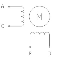
Two-phase bipolar stepper motor with four leads.
The above diagram shows a standard bipolar stepper motor. To control this with the DRV8824/DRV8825, connect stepper leads A and C to board outputs A1 and A2, respectively, and stepper leads B and D to board outputs B1 and B2, respectively. Note that if you happen to swap which way the wires are connected for any coil, the stepper motor will turn in the opposite direction, and if you happen to pair up wires from different coils, the motor should be noticeably erratic when you try to step it, if it even moves at all. See the DRV8824 or DRV8825 datasheet for more information.
If you have a six-lead unipolar stepper motor as shown in the diagram below:

Two-phase unipolar stepper motor with six leads.
you can connect it to the DRV8824/DRV8825 as a bipolar stepper motor by making the bipolar connections described in the section above and leaving stepper leads A’ and B’ disconnected. These leads are center taps to the two coils and are not used for bipolar operation.
If you have an eight-lead unipolar stepper motor as shown in the diagram below:
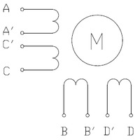
Two-phase unipolar stepper motor with eight leads.
you have several connection options. An eight-lead unipolar stepper motor has two coils per phase, and it gives you access to all of the coil leads (in a six-lead unipolar motor, lead A’ is internally connected to C’ and lead B’ is internally connected to D’). When operating this as a bipolar stepper, you have the option of using the two coils for each phase in parallel or in series. When using them in parallel, you decrease coil inductance, which can lead to increased performance if you have the ability to deliver more current. However, since the DRV8824/DRV8825 actively limits the output current per phase, you will only get half the phase current flowing through each of the two parallel coils. When using them in series, it’s like having a single coil per phase (like in four-lead bipolar steppers or six-lead unipolar steppers used as bipolar steppers). We recommend you use a series connection.
To connect the phase coils in parallel, connect stepper leads A and C’ to board output A1, stepper leads A’ and C to board output A2, stepper leads B and D’ to board output B1, and stepper leads B’ and D to board output B2.
To connect the phase coils in series, connect stepper lead A’ to C’ and stepper lead B’ to D’. Stepper leads A, C, B, and D should be connected to the stepper motor driver as normal for a bipolar stepper motor (see the bipolar stepper connections above).
Related products


Related categories


Home | Forum | Blog | Support | Ordering Information | Wish Lists | Distributors | BIG Order Form | About | Contact
© 2001–2024 Pololu Corporation
