Support » Pololu A-Star 32U4 User’s Guide » 5. A-Star 32U4 Prime »
5.2. A-Star 32U4 Prime pinout and components
Pinout
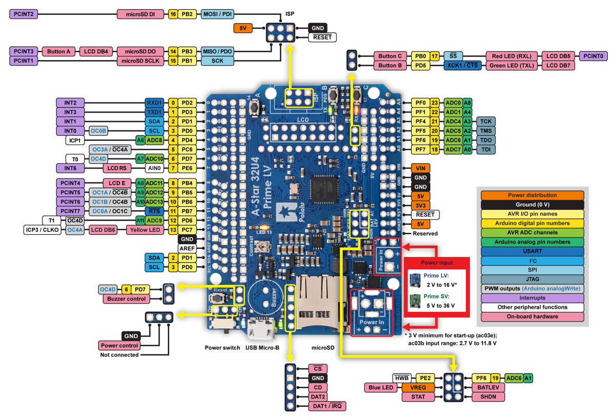 |
This diagram identifies the I/O and power pins on the A-Star 32U4 Prime (LV and SV versions); it is also available (along with the power distribution diagram below) as a printable PDF (1MB pdf). For more information about the ATmega32U4 microcontroller and its peripherals, see Atmel’s ATmega32U4 documentation.
The outermost rows of pins of the A-Star 32U4 Prime correspond to the pins on an Arduino Leonardo, and each is duplicated on a second inner row for more convenient access. Printed on the A* circuit board are indicators that you can use to quickly identify each I/O pin’s capabilities: a triangle by the inner through hole means the pin can be used as an analog input, and a square wave symbol next to the hole pair means the pin can be used as a PWM output.
Additional rows of power and ground pins also run along most of the I/O pins to allow easy connections to devices like sensors and servos. The innermost pin is ground, and the second-innermost is power, which is not connected by default. The power pins are split into three buses: one bus for pins A0–A4 along the bottom, and two buses along the top, split between digital pins 7 and 8. You can configure each bus separately by using a jumper to connect it to a voltage source of your choice. (Access points for 5V and VIN are adjacent to the A0–A4 bus, so it can be conveniently connected to either supply with a shorting block.)
 |
Compatibility with Arduino shields and accessories
The A-Star 32U4 Prime matches the Arduino Leonardo and the Arduino Uno R3 in the shape of its circuit board and the arrangement of its pins. Furthermore, it uses the same ATmega32U4 microcontroller as the Leonardo, running at the same voltage and frequency, so the A* should generally work with any shield or accessory that is compatible with the Leonardo (including our Zumo Robot for Arduino).
LEDs
The A-Star 32U4 Prime has five indicator LEDs.
A blue power LED located next to the power switch indicates when the onboard regulator is active (an external power supply is connected and the switch is turned on).
A green power LED next to the USB connector indicates when the USB bus voltage (VBUS) is present.
A yellow user LED is connected to Arduino pin 13, or PC7. You can drive this pin high in a user program to turn this LED on. The A-Star 32U4 Bootloader fades this LED on and off while it is waiting for a sketch to be loaded.
A green user LED is connected to PD5 and lights when the pin is driven low. While the board is running the A-Star 32U4 Bootloader or a program compiled in the Arduino environment, it will flash this LED when it is transmitting data via the USB connection.
A red user LED is connected to Arduino pin 17, or PB0, and lights when the pin is driven low. While the board is running the A-Star 32U4 Bootloader or a program compiled in the Arduino environment, it will flash this LED when it is receiving data via the USB connection.
The AStar32U4Prime library contains functions that make it easier to control the three user LEDs. All three user LED control lines are also LCD data lines, so you will see them flicker when you update the LCD. The green and red user LEDs also share I/O lines with pushbuttons (see below).
Pushbuttons
The A-Star 32U4 Prime has four pushbuttons: a reset button next to the power switch and three user pushbuttons located along the right edge of the board. The user pushbuttons, labeled A, B, and C, are on Arduino pin 14 (PB3), PD5, and Arduino pin 17 (PB0), respectively. Pressing one of these buttons pulls the associated I/O pin to ground through a resistor.
The three buttons’ I/O lines are also used for other purposes: pin 14 is MISO on the SPI interface, PD5 and pin 17 control the green and red user LEDs, and all three pins are LCD data lines. Although these uses require the pins to be driven by the AVR (or SPI slave devices in the case of MISO), resistors in the button circuits ensure that the A-Star will not be damaged even if the corresponding buttons are pressed at the same time, nor will SPI or LCD communications be disrupted. The functions in the AStar32U4Prime library take care of configuring the pins, reading and debouncing the buttons, and restoring the pins to their original states.
Note that button A cannot be used if the microSD CS pin is tied to ground with a jumper (see microSD card connector and level shifters below).
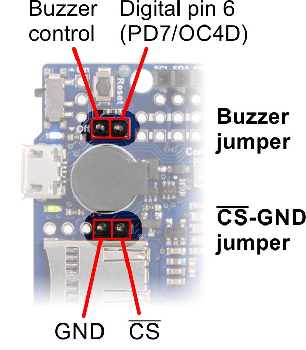 |
Buzzer and CS-GND jumpers on the A-Star 32U4 Prime. |
|---|
Buzzer
The assembled versions of the A-Star 32U4 Prime come with a buzzer that can be used to generate simple sounds and music. The buzzer is not present on the SMT-only versions, but the buzzer driver circuit is still populated, allowing you to solder in your own buzzer or speaker. The stock buzzer is available as part of the A-Star 32U4 Prime accessory pack.
A through-hole jumper next to the buzzer provides a way to connect the buzzer input to digital pin 6 (which also serves as OC4D, a hardware PWM output from the AVR’s 10-bit Timer4). If you alternate between driving the buzzer pin high and low at a given frequency, the buzzer will produce sound at that frequency. You can play notes and music with the buzzer using functions in the AStar32U4PrimeBuzzer library.
microSD card connector and level shifters
Some versions of the A-Star 32U4 Prime include an onboard microSD card connector that enables the microcontroller to read from and write to microSD memory cards. The card socket is connected to the SPI interface on the ATmega32U4 through level-shifting circuits, allowing the 5 V microcontroller to safely communicate with standard 3.3 V SD cards. DI, DO, and SCLK on the card are connected to MOSI, MISO, and SCK on the AVR, respectively. The Arduino SD library can be used to access the file system on an inserted microSD card.
A fourth pin, CS (chip select), must be held low to enable communication with the microSD card in SPI mode. This can be done by connecting one of the microcontroller’s I/O lines to CS (the SD library examples use digital pin 4 by default) and driving the pin low to select the microSD card. The CS line also controls whether the output of the DO level shifter is enabled: when CS is high, the level shifter places its output into a high-impedance state, allowing the MISO line to be driven by other SPI slave devices, used as an LCD control line, or read as a pushbutton input.
Alternatively, you can tie CS low more easily by shorting it to the adjacent ground pin, causing the microSD card to always be selected and the DO level shifter output to always be enabled. This allows you to avoid using an extra I/O line and making an additional connection, but the DO level shifter output will override the pushbutton on the same pin and prevent any presses on button A from being detected. You should remove the CS-GND jumper when no microSD card is present, as asserting CS with no microSD card inserted can put the DO level shifter output into an undefined state.
The CD (card detect) pin next to the connector can be used to detect the presence of a microSD card: it is floating when a card is inserted and shorted to ground when a card is not present. Two additional SD data lines (DAT1 and DAT2), which are unused in SPI mode, are also broken out for advanced uses.
LCD
The A-Star 32U4 Prime has a mounting location for a 2×7 header where you can connect a character LCD with the common HD44780 parallel interface (109k pdf). The A* is optionally available with a male header installed here and an 8×2 character LCD (with corresponding female header) included; on other versions, you can add your own display using the connectors of your choice. A larger LCD can be connected with a ribbon cable and optionally a shrouded box header.
The LCD control lines are broken out to a column of through holes next to the LCD connector, labeled on the back side of the board. By default, some of these are connected to I/O lines from the ATmega32U4 to allow control of the LCD in 4-bit mode, but you can remap the connections by cutting the surface-mount jumpers indicated in the picture below and making new connections between I/O lines and LCD control pins.
 |
The AStar32U4PrimeLCD library provides functions to display data on a connected LCD. It is designed to gracefully handle alternate use of the LCD data lines by only changing pin states when needed for an LCD command, after which it will restore them to their previous states. This allows the LCD data lines to be used for other functions (such as pushbutton inputs and LED drivers).
Other connectors
The A-Star 32U4 includes a USB Micro-B connector that can be used to connect to a computer’s USB port via a USB A to Micro-B cable (not included). The USB connection can be used to transmit and receive data from the computer, and a preloaded USB bootloader makes it possible to program the board over USB. The USB connection can also provide power to the A-Star.
The board also has a 6-pin ISP header that allows it to be programmed with an external programmer, such as our USB AVR programmer v2.1. Pin 1 of the header is indicated with a small dot and has an octagonal shape. Three of the pins on this header can be used as an SPI interface or as general-purpose digital I/O, as labeled on the back side of the board and shown in the pinout diagram. In the Arduino environment, you can refer to these three pins using either their pin numbers or the names of their SPI functions (which are defined as aliases); for example, digitalRead(15) and digitalRead(SCK) are equivalent. If you have an SMT-only version of the A-Star, it is possible to solder a shrouded box header to this location; the outlines on the board indicate the correct connector orientation.
Power
The A-Star 32U4 Prime can either be powered directly from the USB 5 V supply or from an external voltage source, which is regulated to 5 V by its onboard switching regulator. The slide switch on A* controls whether the external source is connected to the input of the regulator, providing a convenient way to switch off external power to the A-Star without unplugging any connections. The adjacent set of three pins provides a place to connect your own power switch: to enable external power, connect the middle pin to ground (accessible through the upper pin).
When the A-Star is connected to a computer via USB, it will receive 5V power even when the power switch is off. This can be useful if you want to upload or test a program without drawing external power (to avoid draining a battery pack, for example).
The board’s power selection circuit uses the TPS2113A power multiplexer from Texas Instruments to choose whether its 5 V supply is sourced from USB or an external supply via the regulator, allowing both sources to be connected at the same time and enabling the A-Star to safely and seamlessly transition between them. The TPS2113A is configured to select external power unless the regulator output falls below about 4.5 V. If this happens, it will select the higher of the two sources, which will typically be the USB 5 V bus voltage if the A* is connected to USB. The currently selected source is indicated by the STAT pin in the middle of the board; this pin is an open-drain output that is low if the external power source is selected and high-impedance if the USB supply is selected. The current limit of the TPS2113A is set to about 1.9 A. For more information about the power multiplexer, see the TPS2113A datasheet (1k redirect).
In some situations, it might be undesirable for the A-Star 32U4 Prime to draw power from an external source when it is connected to USB, even if the power switch is left on. If this is the case, the regulator can be disabled by driving the regulator shutdown pin, SHDN, high; this shuts down the regulator and causes the power mux to fall back to USB power. For example, this could allow a battery-powered system to automatically turn off the regulator while it is connected to a computer.
The input voltage range of the regulator depends on the particular version of the A-Star 32U4 Prime:
- LV (ac03b): 2.7 V to 11.8 V (see Section 5.3 for regulator details)
- LV (ac03e): 2 V to 16 V (see Section 5.3 for regulator details)
- SV: 5 V to 36 V (see Section 5.4 for regulator details)
Reverse-protected and switched power inputs: The connection points labeled “Power In” are power inputs with reverse-voltage protection that are controlled by the power switch. These are the recommended pins to use when connecting an external power supply because they allow the A-Star’s reverse-voltage protection circuit to help prevent it from being damaged by accidentally-reversed power connections, and they enable the A-Star’s power switch to disconnect the supply.
A number of different connectors can be soldered to the board and used to provide power, including a DC barrel jack or a 3.5 mm screw terminal block (the assembled versions of the board come with one or both of these populated).
Warning: You must never connect different power sources to multiple Power In locations at the same time, as doing so will create a short between the supplies.
VIN power output (or alternative input): When power is supplied through the Power In pins, the VIN pin can be used as an output to supply reverse-protected and switched power to other devices. Alternatively, the external supply can be connected directly between VIN and GND, bypassing the reverse-voltage protection and power switch.
5V power output: This pin provides access to the board’s 5 V supply, which comes from either the USB 5 V bus voltage or the onboard switching regulator, depending on which power sources are connected and enabled. Note that some of the available current on the 5 V line is used by the board itself (typically at least 30 mA, but potentially much more if peripherals like the buzzer are active) or used to provide current for the GPIO pins or 3.3 V regulator (see below).
3V3 power output: This pin gives access to the output of the onboard 3.3 V linear regulator. The microSD card, if present, draws power from the 3.3 V line; the remainder (up to a few hundred milliamps) is available for powering external circuits or devices.
When the A-Star 32U4 Prime is being powered through Power In, the sum of the 5V output current, 3V3 output current, GPIO output current, and current used by the board itself should not exceed the maximum current that the switching regulator can provide.
In a battery-powered application, it might be useful for the A-Star to monitor the battery’s voltage level. The BATLEV pin provides access to a voltage divider that outputs a fraction of the VIN voltage (one-third on the ac03b LV, one-fourth on the ac03e LV, and one-eighth on the SV), and this voltage can be read by connecting it to the adjacent analog pin 1 (A1) (or another analog input). The readBatteryMillivoltsLV3(), readBatteryMillivoltsLV4(), and readBatteryMillivoltsSV() functions in the AStar32U4 library can be used to determine the battery voltage from this reading.
Related products


Home | Forum | Blog | Support | Ordering Information | Wish Lists | Distributors | BIG Order Form | About | Contact
© 2001–2024 Pololu Corporation
