Support » Sample Project: Wixel USB Joystick »
3. Construction
To begin converting an input device with a Wixel, you first need to make the appropriate electrical connections and integrate the Wixel into the device physically. This section of the guide demonstrates the construction process with the Tandy joystick we converted.
Step 1: Disassemble the joystick and look at its wiring.
First, you need to open up your input device to allow access to the pins on its buttons and potentiometers.
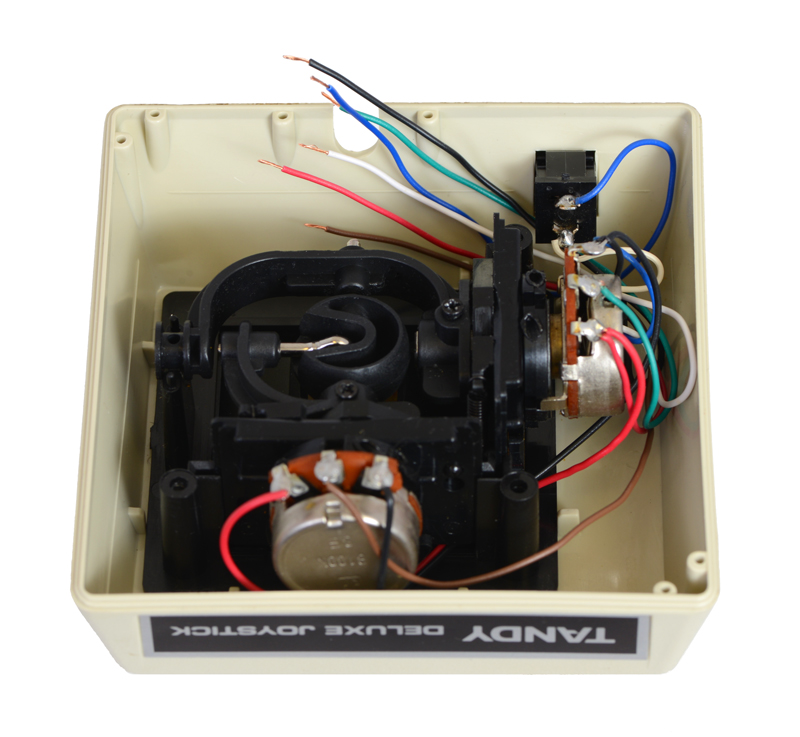
 |
Inside the unmodified Tandy joystick. |
|---|
In the case of this Tandy joystick, we could see that the wires from the components went directly into the joystick’s original cable, so we were able reuse those wires to connect the components to the Wixel.
In some other input devices, such as certain gamepads, the components might instead be connected to a microcontroller or other logic inside the device. To convert such a device, you might need to make new wire connections between the components and the Wixel, and you might need to cut existing connections to ensure the original circuits don’t interfere with the Wixel’s inputs.
Step 2: Determine how to wire the buttons and potentiometers to the Wixel.
The Wixel’s Joystick App supports two kinds of inputs: digital signals can be used to represent joystick buttons, and analog voltages can be used to represent joystick axis positions. Each physical button and potentiometer in the device needs to be wired to the Wixel appropriately so that its state can be read by the Wixel.
Button or switch
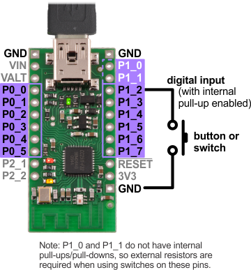 |
Diagram for connecting a button or switch to the Wixel for use with the Joystick App. |
|---|
Pushbuttons and switches can be connected to any of the Wixel’s digital I/O pins on Port 0 (P0_0 through P0_5) or Port 1 (P1_0 through P1_7).
The picture on the right shows the easiest way to do this: the button or switch should be connected between the selected pin and GND (0 V), and the internal pull-up resistor on the pin should be enabled. (Pull-up settings can be changed when the Joystick App is loaded onto the Wixel, as discussed later in in Section 4.) In this configuration, the input will be pulled high (3.3 V) when the switch is open, and it will fall to 0 V when the switch is closed.
The Joystick App allows you to change how each input maps to a joystick function (for example, you could designate P1_6 to represent Button 0 and P1_3 to represent Button 1), so you have a choice of which input pin to use for each button or switch. However, you should be aware of limitations when using certain pins:
- Using any of the Port 0 pins as a digital input (button) prevents it from being used as an analog input (axis).
- Pins P1_0 and P1_1 do not have internal pull-ups/pull-downs, so you will need to connect an external pull-up or pull-down resistor to use either of these pins with a button or switch.
Our Tandy joystick has two buttons, and we connected them to pins P1_2 and P1_3.
Potentiometer
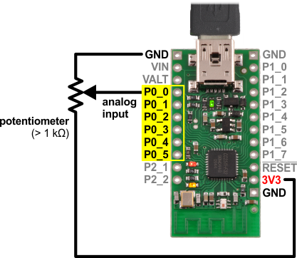 |
Diagram for connecting a potentiometer to the Wixel for use with the Joystick App. |
|---|
Potentiometers can be connected to any of the Wixel’s analog input pins on Port 0 (P0_0 through P0_5).
The picture on the right shows the correct way to connect a potentiometer to an analog input: the end terminals of the potentiometer should be connected between 3V3 (the Wixel’s 3.3 V output) and GND (0 V), and the wiper terminal should be connected to the selected pin. This way, the voltage on the wiper seen by the analog input will change from 0 V at one end of the potentiometer’s range to 3.3 V at the other end.
The potentiometer should have a resistance of at least 1 kilo-ohm so that it does not draw too much current from the 3V3 line. The Tandy joystick contains two 100k potentiometers, one for each axis; we connected them to P0_0 and P0_1.
Caution: The Wixel’s I/O lines are not 5 V tolerant, so you must not connect voltages over 3.3 V to these pins.
Step 3: Solder the button and potentiometer connections to the Wixel.
We prepared the existing wires in our joystick by cutting them and stripping their ends. As discussed in Step 1, we were able to simply connect the wires in this joystick directly to the Wixel, but a different device might require more modification. If you are unsure about the connections you need to make, it might be a good idea to try making temporary connections to the Wixel (e.g. with test leads) and skip to loading the Joystick App onto the Wixel to see if your converted device works as you expect.
 |
Wires cut and stripped inside the joystick. |
|---|
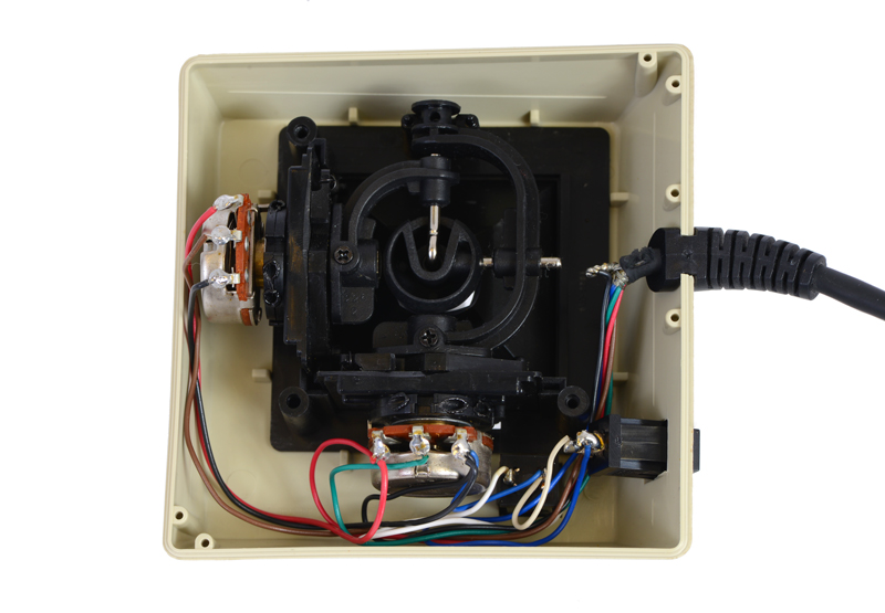
For maximum compactness, we soldered the wires directly to the pins we have chosen on the Wixel.
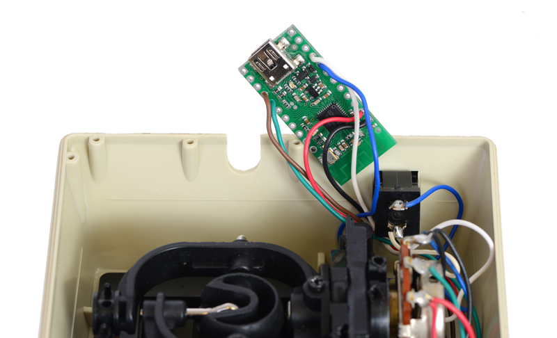 |
Joystick wires soldered to a Wixel. |
|---|
Step 4: Connect a USB cable and mount the Wixel inside the joystick.
Since you might have to reload the app a few times to change the configuration settings, you will need access to the Wixel in order to put it into bootloader mode. This means it is a good idea to mount the Wixel in a way that still allows you to connect P2_2 to 3V3 and to leave the housing of the device open for now.
Once a USB cable is plugged into the Wixel and it is secured, the construction of the device will be complete, and you will be ready to load and configure the Joystick App on the Wixel. We used double-sided foam tape to attach the Wixel to a convenient spot inside the joystick’s housing.
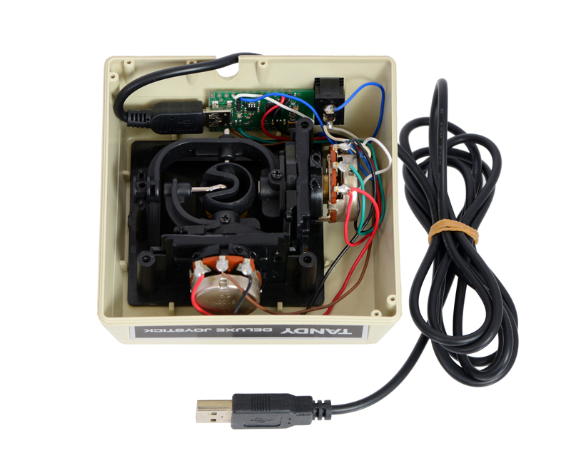 |
Joystick with Wixel mounted inside and USB cable attached. |
|---|
Related products


Home | Forum | Blog | Support | Ordering Information | Wish Lists | Distributors | BIG Order Form | About | Contact
© 2001–2024 Pololu Corporation
