Support » Pololu Dual MC33926 Motor Driver Shield User’s Guide » 4. Using as a General-Purpose Motor Driver »
4.b. Board Connections
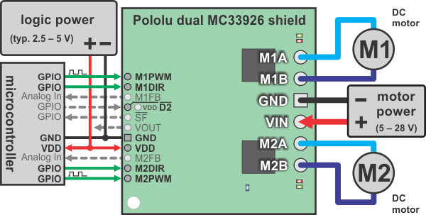 |
Using the dual MC33926 motor driver shield with a microcontroller (gray connections are optional). |
|---|
The above diagram shows the minimum connections typically required to interface this motor driver with a microcontroller. Note that D2 is internally pulled low, which disables the motor outputs; it must either be connected to an I/O line (for dynamic control) or soldered to the neighboring VDD pin to enable the drivers. Only two pins are required per motor: direction control with MxDIR and speed control with MxPWM.
Pinout
The following table explains the board pins in detail. See the MC33926 datasheet (1MB pdf) for even more detailed information about these pins.
| PIN | Default State | Description |
|---|---|---|
| VIN | The connection point for the positive side of the 5 – 28 V motor power supply. | |
| VDD | The connection point for the positive side of the logic power supply (typically 2.5 – 5 V). | |
| VOUT | This pin gives you access to the motor power supply after the reverse-voltage protection MOSFET (see the board schematic in Section 5). It can be used to supply reverse-protected power to other components in the system, but it should not be used for high currents. This pin should only be used as an output. | |
| GND | Ground connection points for logic and motor power supplies. The controlling device and the motor driver must share a common ground. | |
| MxA/B | Output of half-bridge A/B. Each half-bridge connects to one terminal of a DC motor. | |
| MxPWM | LOW | Pulse-width modulation input: a PWM signal on this pin corresponds to a PWM output on the corresponding driver’s motor outputs. When this pin is low, the motor brakes low. When it is high, the motor is on. The maximum allowed PWM frequency is 20 kHz. |
| MxDIR | LOW | Motor direction input. |
| MxFB | Current sense output. The pin voltage is roughly 525 mV per amp of output current. (Note that the voltage on this pin can exceed 3.3 V at high currents, which might make it unsafe to connect to 3.3 V analog inputs. The CS circuit has a 1 kΩ resistor in series with the output, which offers some protection, and the driver has over-current protection that kicks in between 5 A and 8 A, so the risk is low, but the safest approach would be to use a 3.3 V zener diode to clamp the output to ~3.3 V or a voltage divider to scale the output over a range that is appropriate.) | |
| SF | HIGH | Diagnostic output. When both drivers are functioning normally, this pin is internally pulled high. When a driver fault occurs, the IC drives this pin low and the motor outputs are disabled. This pin will also be low whenever D2 is low. Note that the status flag lines from both drivers are tied together. See Section 6.b for information on how to individually access the status flag pins (this is typically not necessary). |
| D2 | LOW | Disables the motor driver outputs when low. A PWM on this pin with MxPWM held high results in drive-coast operation (vs. drive-brake when the PWM is applied to MxPWM and D2 is held high). Toggling this pin will clear any latched faults. Note that the disable lines from both drivers are tied together. See Section 6.b for information on how to individually access the disable pins (this is typically not necessary). |
Simplified Motor Control Truth Table
| Inputs | Outputs | |||||
|---|---|---|---|---|---|---|
| D2 | MxPWM | MxDIR | MxA | MxB | SF | Mode |
| H | H | L | H | L | H | forward |
| H | H | H | L | H | H | reverse |
| H | L | X | L | L | H | brake |
| L | X | X | Z | Z | L | coast |
L = LOW, H = HIGH, X = HIGH or LOW, Z = high impedance
The above table assumes there are currently no driver faults.
Power Considerations
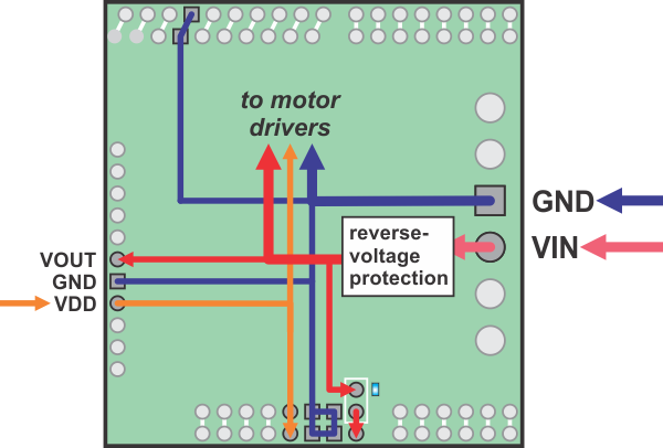 |
Dual MC33926 motor driver shield power buses when not used with an Arduino. |
|---|
The shield must be supplied with 5 to 28 V through the large VIN and GND pads on the right side of the board. A high-side reverse-voltage protection MOSFET prevents the shield from being damaged if shield power is inadvertently connected backwards.
It is important that you use a power source that is capable of delivering the current your motors will require. For example, alkaline cells are typically poor choices for high-current applications, and you should almost never use a 9V battery (the rectangular type with both terminals on the same side) as your motor power supply.
Logic power at the same level as your controlling device should be supplied to the VDD pin. This will typically be between 2.5 and 5 V.
Please see the MC33926 datasheet and Section 3.c for more power considerations and for information about shield power dissipation.
Motor Considerations
The motor considerations are the same as those detailed in Section 3.c.
Related products


Home | Forum | Blog | Support | Ordering Information | Wish Lists | Distributors | BIG Order Form | About | Contact
© 2001–2024 Pololu Corporation
