Attention: If you are assembling a Zumo Robot for Arduino using the Zumo Shield for Arduino, please follow the more specialized assembly instructions for that product instead of the ones in this document!
Please follow these instructions carefully to assemble your Zumo properly.
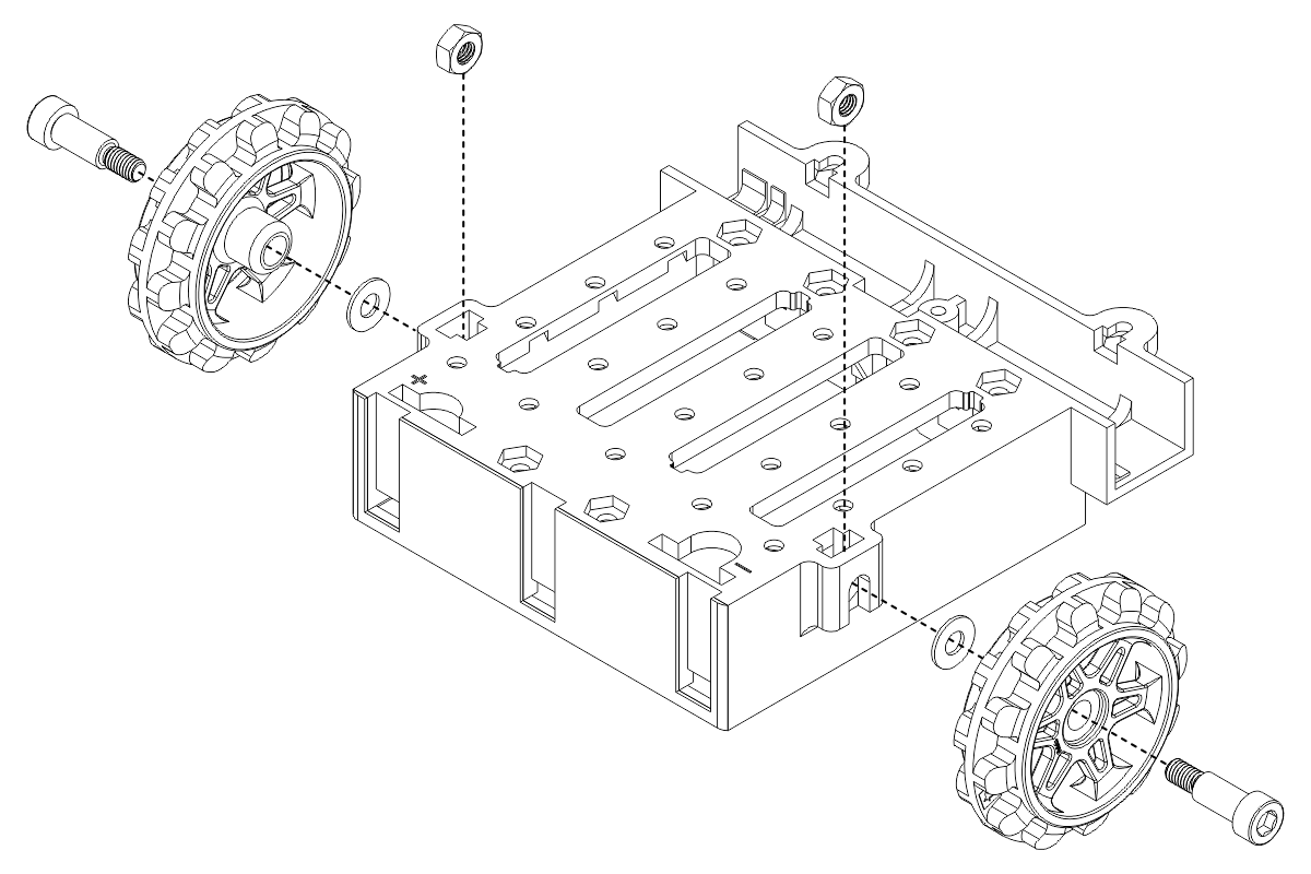
Idler sprockets
- Place an M3 nut in each of the two side slots near the rear of the chassis. The slots are sized so that nuts will not be able to rotate within them.
- Place an idler sprocket on each shoulder bolt, followed by a washer. The protruding side of the sprocket hub should face the same direction as the threaded end of the bolt (in toward the chassis).
- Insert the shoulder bolts through the side of the chassis into the nut. Use a 3 mm hex key (Allen wrench) to tighten the bolts until the washers are snug against the chassis. Be careful not to overtighten the shoulder bolts as doing so can bend the washers.
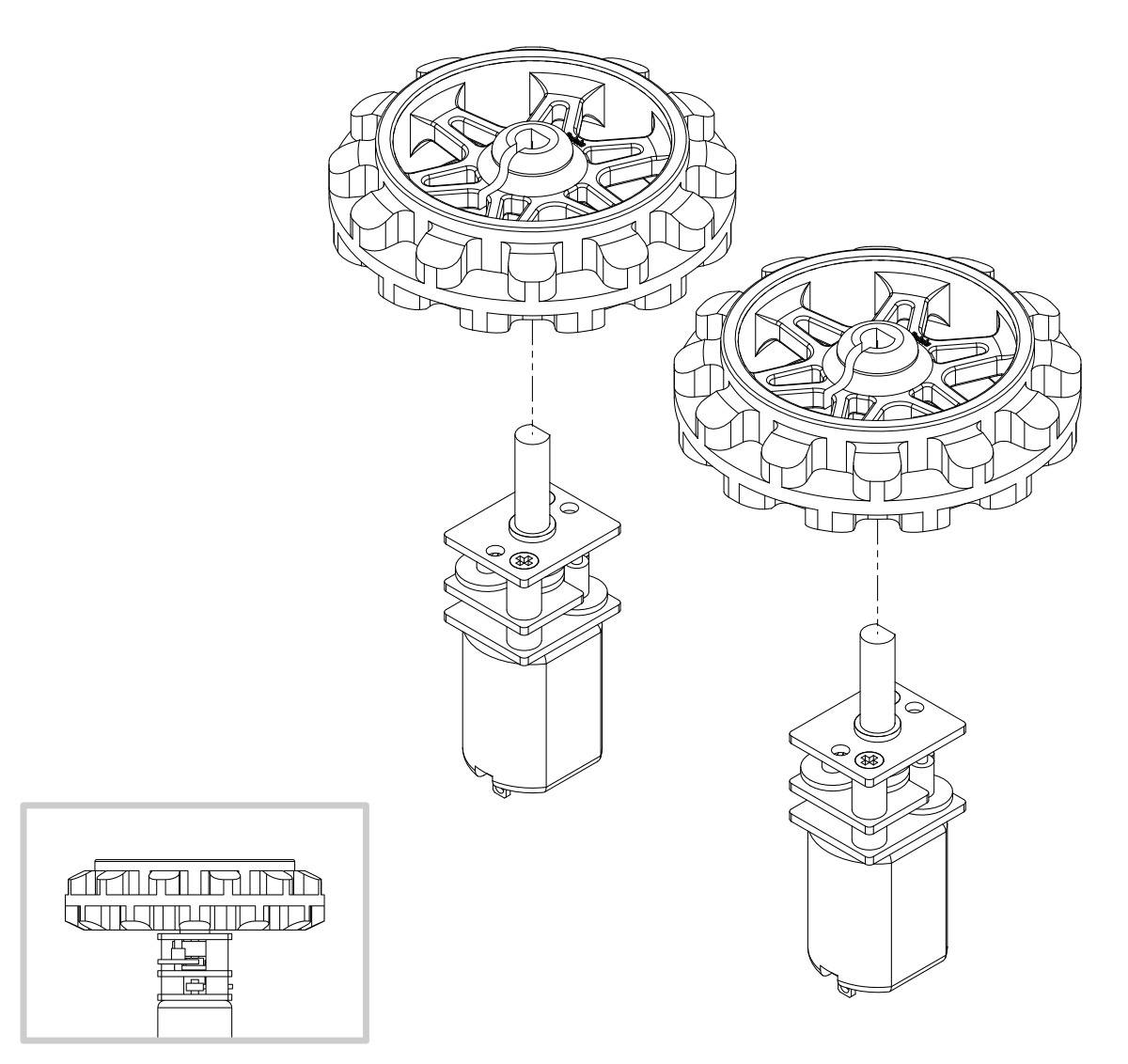
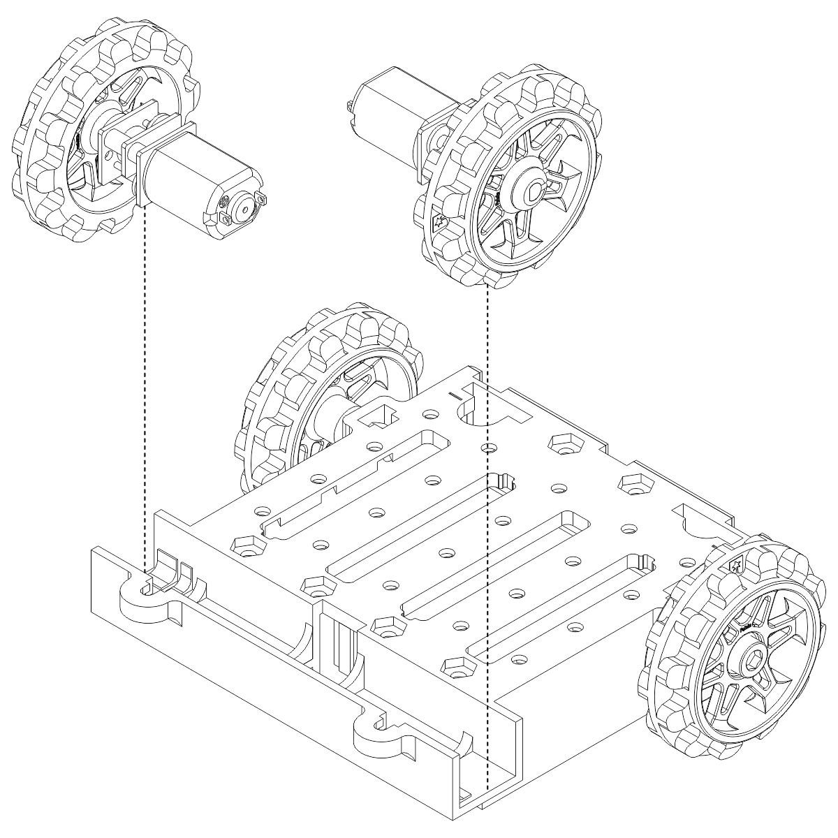
Motors and drive sprockets
- Solder any connections you want to make to your motors (such as wires and bypass capacitors) before installing the motors in the chassis, as you will not be able to access the motor leads easily once the acrylic mounting plate is in place.
- Press the output shafts of the motors into the drive sprockets, with the raised lip on one side of the sprocket facing away from the motor. The end of the gearbox shaft should end up flush with the outside of the sprocket. A good way to do this is to set the wheel on flat surface (like a table top) and press the motor shaft into the wheel until it contacts the surface.
- Place the motors into the channel in the front of the chassis, aligning the gearbox with the grooves in the channel. The front plate of the gearbox should be even with the edge of the chassis.
Mounting plate
There are two types of mounting holes sized for #2-56 screws in the rear portion of the chassis:
- The middle four rows of holes have a recess for a nut on the interior of the chassis. These holes can be used to secure the mounting plate or other components directly to the chassis, as demonstrated by the screw on the left side of the picture below.
- The four holes along the front edge of the chassis and the two holes along the rear edge have a recess for a nut on the exterior of the chassis. These holes can be used to secure a component to the mounting plate alone, as demonstrated by the standoff on the right side of the picture below, allowing the mounting plate to be removed from the chassis without having to first detach the component.
The mounting plate is secured to the chassis with screws through the two rounded tabs that protrude from the front edge, along with any number of the interior-nut mounting holes in the rear.
- Decide which mounting holes on the chassis and mounting plate you will use. If you want to use any exterior-nut holes, place nuts in the corresponding recesses on top of the chassis.
- Peel the protective masking off the plate and place it on top of the chassis such that the cut-outs for the battery terminals match those on the chassis below. To get the front of the plate under the drive sprockets, you will need to angle it and slide one side in first.
- In each of the two front tabs and your choice of the interior-nut holes along the rear, insert a #2-56 machine screw through the mounting plate and chassis and tighten it against a nut inside the chassis. You can line up the nut by feel, or you could try temporarily taping the nuts inside the recesses in the chassis. Note: if you are also adding a basic sumo blade, you should place its mounting tabs on top of the acrylic mounting place so that its holes line up with the two front-tab holes and use the #2-56 machine screws to mount both the blade and the acrylic mounting plate to the chassis. Do not try to adjust the angle of the sumo blade while it is mounted to the chassis as this can crack the acrylic mounting plate.
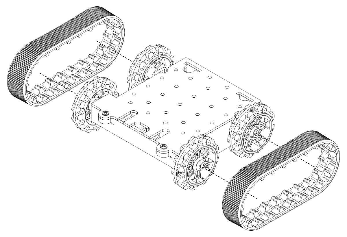
- At this point, you can add the silicone tracks by stretching them around the sprockets on each side of the chassis, or you can leave this for the final step.
 |
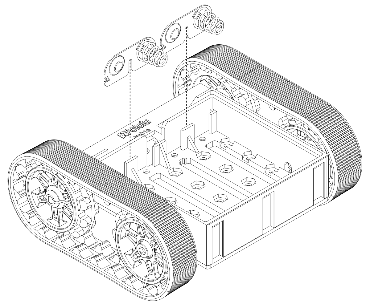
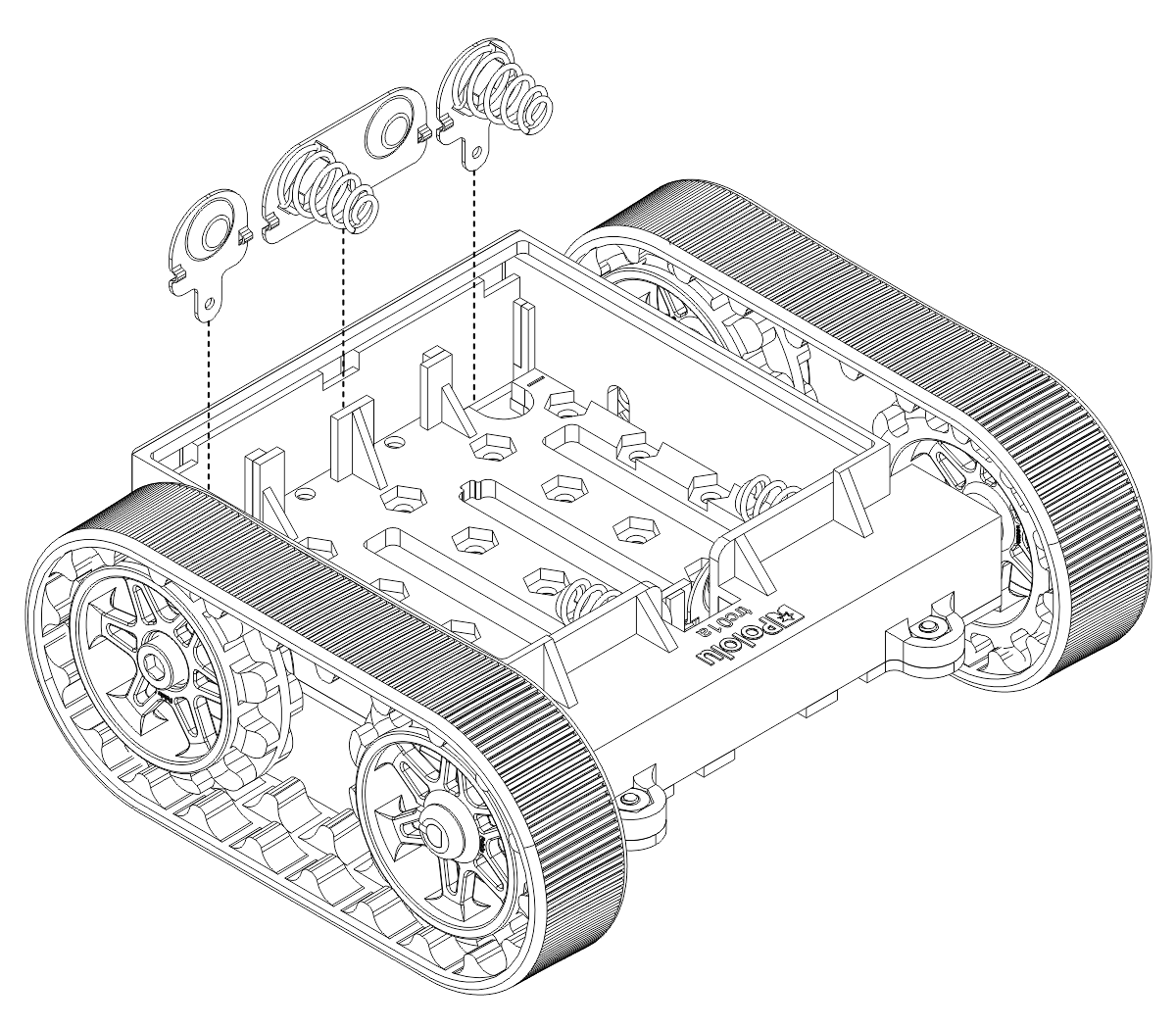
Battery contacts
- Turn the chassis over and install the battery terminal contacts as shown in the diagrams below. Note that the two individual contacts should be inserted into the chassis so that their solder tabs protrude through the holes in the top of the chassis and can be accessed from the exterior. You might want to use some glue (hot-melt adhesive works well) or double-sided tape to hold the two individual contacts in place if you will not be soldering them to something rigid.
- Insert four AA batteries (the cut-out slots in the battery holder indicate the proper battery orientation) and snap the battery cover onto the bottom of the chassis.