Support » Pololu Dual VNH5019 Motor Driver Shield User’s Guide » 3. Getting Started with an Arduino »
3.c. Shield Connections
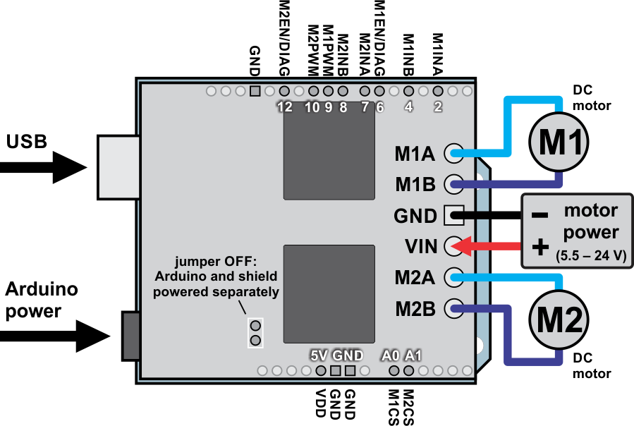 |
Dual VNH5019 motor driver shield with an Arduino (shield and Arduino powered separately). |
|---|
All of the necessary logic connections between the Arduino and the motor driver shield are made automatically when the shield is plugged into the Arduino. However, the shield’s power connections must be made directly to the shield itself via its large VIN and GND pads. The picture above shows the typical connections involved in using this board as an Arduino shield.
Default Arduino Pin Mappings
The following table shows how the shield connects your Arduino’s pins to the motor drivers’ pins:
| Arduino Pin | VNH5019 Driver Pin | Basic Function |
|---|---|---|
| Digital 2 | M1INA | Motor 1 direction input A |
| Digital 4 | M1INB | Motor 1 direction input B |
| Digital 6 | M1EN/DIAG | Motor 1 enable input/fault output |
| Digital 7 | M2INA | Motor 2 direction input A |
| Digital 8 | M2INB | Motor 2 direction input B |
| Digital 9 | M1PWM | Motor 1 speed input |
| Digital 10 | M2PWM | Motor 2 speed input |
| Digital 12 | M2EN/DIAG | Motor 2 enable input/fault output |
| Analog 0 | M1CS | Motor 1 current sense output |
| Analog 1 | M2CS | Motor 2 current sense output |
See the Pinout portion of Section 4.b for detailed descriptions of the VNH5019 driver pins and Section 5 for a schematic diagram of the shield. See Section 6.a for instructions on how to customize your board’s Arduino pin mappings if the above defaults are not convenient.
Power Connections and Considerations
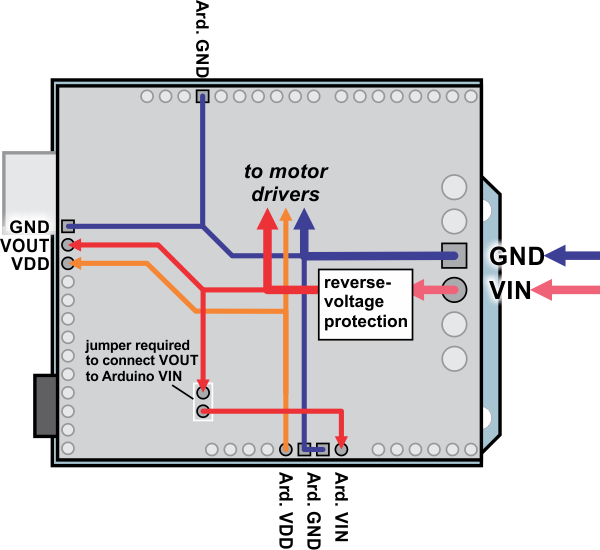 |
Dual VNH5019 motor driver shield power buses when connected to an Arduino. |
|---|
In the shield’s default state, the motor driver shield and Arduino are powered separately. When used this way, the Arduino must be powered via USB, its power jack, or its VIN pin, and the shield must be supplied with 5.5 to 24 V through the large VIN and GND pads on the right side of the board. Attempting to power the shield through other means, such as from the Arduino or through the small VOUT pin, can permanently damage both the Arduino and the shield (only the large power traces on the right side of the shield are designed to handle the high currents involved in powering motors). A high-side reverse-voltage protection MOSFET prevents the shield from being damaged if shield power is inadvertently connected backwards (for supply voltages up to 16 V; higher voltages can damage the driver if connected in reverse). Logic power, VDD, is automatically supplied by the Arduino.
Note that the motor driver features over-voltage protection that can activate at voltages as low as 24 V, so we do not recommend using it with 24 V batteries (such batteries can significantly exceed 24 V when fully charged).
It is important that you use a power source that is capable of delivering the current your motors will require. For example, alkaline cells are typically poor choices for high-current applications, and you should almost never use a 9V battery (the rectangular type with both terminals on the same side) as your motor power supply.
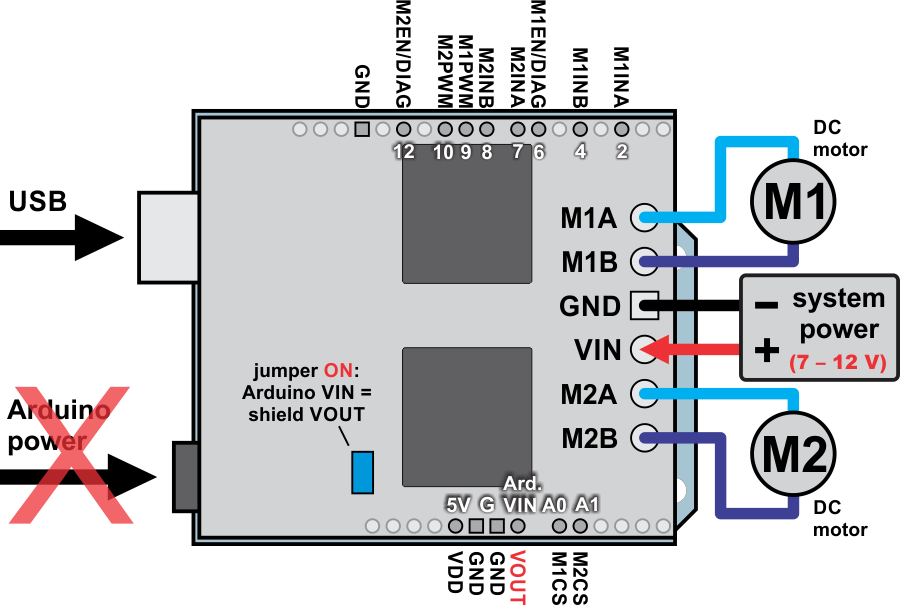 |
Dual VNH5019 motor driver shield with an Arduino (Arduino powered by the shield). |
|---|
It is also possible to power your Arduino directly from the motor shield, as shown in the diagram above, which eliminates the need for a separate Arduino power supply. When the ARDVIN=VOUT shorting block is in place, the shield’s reverse-protected input power, VOUT, is connected to the Arduino’s VIN pin. (When power is connected properly, VOUT is essentially the same as the shield’s VIN.) The Arduino’s power jack must remain disconnected at all times in this configuration.
Warning: When powering the Arduino from the motor shield, you must never connect a different power supply to the Arduino’s VIN pin or plug a power supply into the Arduino’s power jack, as doing so will create a short between the shield’s power supply and the Arduino’s power supply that could permanently damage both the Arduino and the motor shield. In this case, it is also important that your shield power supply is an acceptable voltage for your Arduino, so the full shield operating voltage range of 5.5 – 24 V probably will not be available. For example, the recommended operating voltage of the Arduino Uno is 7 – 12 V.
Note that the shorting block just routes the motor power to the Arduino VIN pin, so plugging in USB with this shorting block in place is just like plugging in USB with the Arduino powered from its power jack. On standard Arduinos we recommend against plugging a powered Arduino into USB (see this forum post for more information), but on some Arduino-compatible boards such as the A-Stars, this is completely safe.
Motor Connections and Considerations
This motor driver shield has two motor channels, M1 and M2, each of which can be used to independently control a bidirectional brushed DC motor. Each motor channel is comprised of a pair of pins—MxA and MxB—that connect to the two terminals of a DC motor and can deliver a continuous 12 A (30 A peak).
Note: It is also possible to connect a single brushed DC motor to both motor channels simultaneously to deliver nearly twice the current as is available from a channel by itself. See Section 7 for more information.
Each VNH5019 motor driver IC has a maximum continuous current rating of 30 A. However, the chips by themselves will overheat at lower currents. In our tests on a sample unit, we were able to deliver 30 A for a few milliseconds, 20 A for several seconds, 15 A for over a minute, and 12 A for around five minutes. At 6 A, the chip just barely gets noticeably warm to the touch. The actual current you can deliver will depend on how well you can keep the motor driver cool. The shield’s printed circuit board is designed to draw heat out of the motor driver chips, but performance can be improved by adding a heat sink.
This product can get hot enough to burn you long before the chip overheats. Take care when handling this product and other components connected to it.
Many motor controllers or speed controllers can have peak current ratings that are substantially higher than the continuous current rating; this is not the case with these motor drivers, which have a 30 A continuous rating and over-current protection that can activate at currents as low as 30 A (50 A typical). Therefore, the stall current of your motor should not be more than 30 A. (Even if you expect to run at a much lower average current, the motor can still draw short bursts of high currents, such as when it is starting, if special steps are not taken.)
If your motor has a stall current over the driver’s continuous current rating of 12 A per channel, we recommend you take extra steps to make sure that your motor will not be exposed to loads that will cause it to exceed 12 A for prolonged periods of time (or you take extra steps to keep the motor drivers cool, such as increasing air flow or adding heat sinks). Exceeding 12 A for long durations should not damage the shield, but it will eventually activate the driver’s thermal protection, which might result in inadequate performance for your application.
It is not unusual for the stall current of a motor to be an order of magnitude (10×) higher than its free-run current. If you do not know your motor’s stall current, you can approximate it by measuring the current it draws while held stalled at a lower voltage (such as when powered from a single battery cell) and then scaling that value linearly with voltage. For example, the stall current of a motor at 6 V is six times the stall current of that motor at 1 V. Another, less accurate method is to use a multimeter to measure the resistance between the motor terminals and then use Ohm’s law to compute the stall current I at voltage V: I = V/R. This last method generally is not as reliable because it can be difficult to measure such small resistances accurately.
Occasionally, electrical noise from a motor can interfere with the rest of the system. This can depend on a number of factors, including the power supply, system wiring, and the quality of the motor. If you notice parts of your system behaving strangely when the motor is active, first double-check that your power supply is adequate, then consider taking the following steps to decrease the impact of motor-induced electrical noise on the rest of your system:
|
||
|

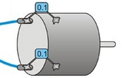
- Solder a 0.1 µF ceramic capacitor across the terminals of your motors, or solder one capacitor from each terminal to the motor case (see the pictures to the right). For the greatest noise suppression, you can use three capacitors per motor (one across the terminals and one from each terminal to the case).
- Make your motor leads as thick and as short as possible, and twist them around each other. It is also beneficial to do this with your power supply leads.
- Route your motor and power leads away from your logic connections if possible.
- Place decoupling capacitors (also known as “bypass capacitors”) across power and ground near any electronics you want to isolate from noise. These can typically range from 10 uF to a few hundred uF.


Home | Forum | Blog | Support | Ordering Information | Wish Lists | Distributors | BIG Order Form | About | Contact
© 2001–2024 Pololu Corporation
