Support » Pololu Wixel User’s Guide »
11. The Wixel USB Bootloader
The Wixel comes with a USB bootloader that can be used in conjunction with the Wixel Configuration Utility or WixelCmd to upload apps to the Wixel (no external programmer is required). This section documents some technical details of the bootloader and is intended for advanced users.
Flash Memory Sections
The bootloader occupies the first 1 KiB (1024 bytes) and the last 2 KiB of the CC2511F32’s flash memory. Those sections of memory are protected to prevent accidental corruption of the bootloader. The remaining 29 KiB of flash, known as the application section, is available for the app. The bootloader places no restrictions on what data can be written to the application section. However, the bootloader will consider the application to be invalid and not allow any code in the application section to run if the first byte of the application section (address 0x400) is 0xFF, which should never be the case for an application that is compiled correctly.
The CC2511’s standard entry vector and the interrupt vectors are remapped by the bootloader to the beginning of the application section. The application’s entry vector should be placed at 0x400. The first interrupt vector should be at 0x403 and consecutive interrupt vectors should be 8 bytes apart.
The application can put the Wixel into bootloader mode by jumping to address 0x6 using an ljmp instruction.
The block of flash memory from 0x3CC to 0x3FF in the bootloader is used to store some information that can be read by the application:
- Addresses 0x3CC–0x3DD contain the USB device descriptor of the bootloader, as defined in the USB 2.0 Specification.
- Addresses 0x3E0–0x3E3 contain the serial number of the Wixel as a 32-bit unsigned little-endian integer.
- Addresses 0x3E6–0x3FD contain the serial number of the Wixel in USB string descriptor format.
The bytes in the 0x3CC–0x3FF region not mentioned above are reserved and contain only zeros.
Startup Procedure
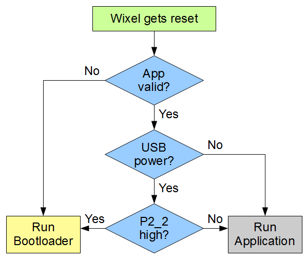 |
When the Wixel resets, it uses this procedure to decide whether to run the bootloader or the app. |
|---|


Home | Forum | Blog | Support | Ordering Information | Wish Lists | Distributors | BIG Order Form | About | Contact
© 2001–2024 Pololu Corporation
