Support » Pololu Simple Motor Controller User’s Guide » 4. Connecting Your Motor Controller »
4.3. Connecting an RC Receiver
Simple Motor Controller can be directly connected to an RC receiver, allowing for wireless, manual motor control. The RC inputs can serve several functions, from directly controlling the motors (RC input mode) to sending signals to an autonomous robot (Serial/USB mode) to providing an RC kill switch (any input mode). The Simple Motor Controller can derive motor speed from a single RC input channel, or it can mix the signals on both RC channels to generate the motor speed, which makes intuitive throttle+steering control of a differential-drive robot possible using a pair of Simple Motor Controllers. A BEC jumper lets the Simple Motor Controller optionally power your RC receiver at 3.3 or 5 V, eliminating the need for a second battery.
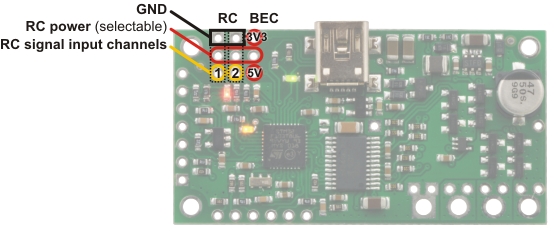 |
Simple Motor Controller 18v7 RC connections. |
|---|
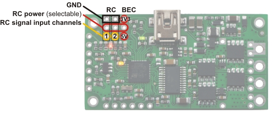 |
Simple High-Power Motor Controller 18v15 or 24v12 RC connections. |
|---|
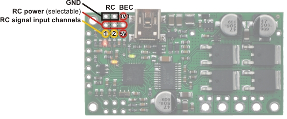 |
Simple High-Power Motor Controller 18v25 or 24v23 RC connections. |
|---|
RC Connections Overview
The RC connection block consists of two channels oriented as columns and a battery elimination circuit (BEC) column for supplying power to the RC receiver. Each channel has a ground pin (outlined in black in the above diagrams), a power pin (outlined in red in the above diagrams), and a signal pin (outlined in yellow in the above diagrams). The RC signal pins can read standard hobby servo RC pulses with peaks anywhere from 2 to 5 V. The included shorting block can be used to supply the power pin row with either 3.3 V or 5 V, which in turn can be used to power an RC receiver.
Note: If you want to connect servos directly to your RC receiver, you must power it separately as the Simple Motor Controller’s regulators cannot supply enough current to power a servo. If your RC receiver is powered separately, you must leave the BEC jumper off to avoid shorting the motor controller’s regulated voltage to your RC receiver’s power source. Your receiver and Simple Motor controller must always have a common ground, even if you power the RC receiver separately.
The channel pins have a 0.1" spacing, which means that a female-female servo extension cable can be used to connect an RC receiver directly to the board.
Simple Wiring Example: Connecting to an RC Receiver
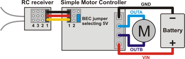 |
Wiring diagram for connecting an RC receiver to a Simple Motor Controller. |
|---|
Using the RC Channels
The Simple Motor Controller is constantly reading the two RC channels and making the measured pulse widths available via the USB and serial interfaces, even when the controller is not in RC mode. For example, you can use the serial interface to read the RC channel values while the motor controller is in analog mode. The RC channels are read with 0.25 µs resolution, and RC pulse frequencies from 10 Hz to 333 Hz are permitted. A number of settings exist for adjusting what constitutes a valid RC signal.
Driving a Motor
In RC mode, the channel values are mapped to motor speed based on the channel calibration values and the mixing mode. We recommend your first step after connecting your RC receiver be to use the Quick Input Setup wizard in the Simple Motor Control Center. The wizard instructs you to move your transmitter control sticks to their extremes and maps stick full forward/right to the maximum forward motor speed, the neutral stick to speed zero, and the stick full back/left to maximum reverse speed. Calibration can have a significant impact on performance.
If mixing mode is disabled, only channel 1 affects motor speed. If mixing mode is set to “right” or “left”, channel 1 is considered the “throttle” input and channel 2 is considered the “steering” input. Left mixing mode obtains motor speed by summing the throttle and steering channels (CH1+CH2) while right mixing mode obtains motor speed by taking the difference of the throttle and steering channels (CH1-CH2). To see why this makes sense, consider a differential-drive robot (a robot with a motor on each side) with a left motor driven by a Simple Motor Controller in left mixing mode and a right motor driven by a Simple Motor Controller in right mixing mode. When throttle is full forward (CH1=max) and steering is neutral (CH2=0), left- and right-mixed motors are both driven forward at full speed and the robot goes forward. When throttle is neutral (CH1=0) and steering is full right (CH2=max), the left mixing results in motor forward at full speed while right mixing results in motor reverse at full speed, so the robot turns right.
As demonstrated above, using both RC channels in mixing mode makes it possible to combine two RC-controlled Simple Motor Controllers to achieve single-stick (mixed) control of a differential drive robot. The following diagram shows how to connect two such motor controllers together:
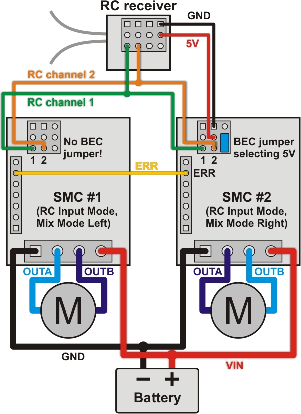 |
Wiring diagram for pairing two Simple Motor Controllers with RC channel mixing. |
|---|
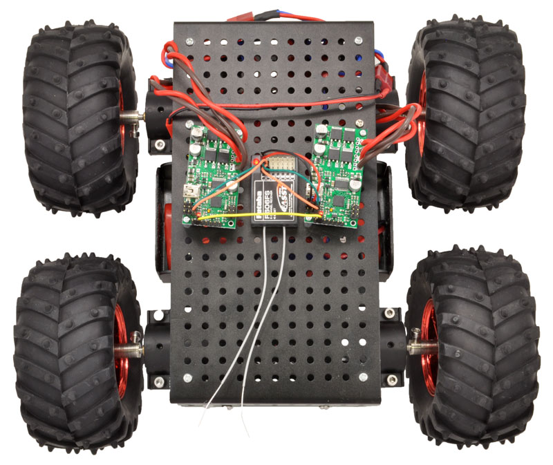
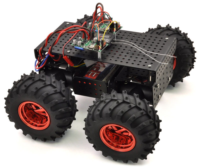
You should configure the controller that drives the right motor as “mixing mode right” and the controller that drives the left motor as “mixing mode left”. You can splice together your own cables or use premade Y splitter cables to connect channels 1 and 2 from your RC receiver to channels 1 and 2 of both controllers as shown in the diagram above. You can also connect the ERR lines of both controllers together to ensure that both controllers stop if either controller experiences an error. The following pictures show a Wild Thumper 4WD chassis being driven by two Simple Motor Controllers in mixed RC mode as depicted in the above wiring diagram:
|
|
Limit/Kill Switches
Unused RC channels can also be used as limit or kill switches. For example, you could use an RC signal as a kill switch to stop your autonomous, serially-controlled robot if it gets into trouble. When configured as a limit or kill switch, if the channel’s value exceeds more than half of its “forward” value, the switch is activated. We recommend you use the Channel Setup Wizard (click the “Learn…” button in the Simple Motor Control Center) for any RC channel you configure as a limit or kill switch.
Related products


Home | Forum | Blog | Support | Ordering Information | Wish Lists | Distributors | BIG Order Form | About | Contact
© 2001–2024 Pololu Corporation
