Support » Pololu Maestro Servo Controller User’s Guide » 7. Wiring Examples »
7.b. Attaching Servos and Peripherals
On the Maestro, any of the channels can be used as RC servo pulse output, as an analog/digital input, or as a digital output. This allows the Maestro to control servos, read button presses, read potentiometer positions, drive LEDs, and more. The channels can be controlled from the user script within the Maestro or externally over TTL-level serial or USB.
Servo
To connect a servo to the Maestro, you must first decide which channel you would like to use. If the channel is not already configured to be in servo mode (the default), then in the Maestro Control Center, under the Channel Settings tab, change that channel to Servo mode and click “Apply Settings”. Connect your servo cable to the channel, being careful not to plug it in backwards. Make sure to connect your servo correctly, or it might be destroyed. The signal (usually white, orange, or yellow) wire should be toward the inside of the board, and the ground wire (usually black or brown) should be closest to the edge of the board.
You will need to connect a DC power supply for your servos. See Section 7.a for powering information.
You can test your servo by setting the target of the servo channel in the Status tab of the Maestro Control Center. If you enable the servo channel by checking the “Enabled” checkbox, you should be able to make the servo move by dragging the slider bar left and right. Now you can control the servos in your script using the SERVO command, or over serial using the “Set Target” command. These commands take arguments in units of quarter-microseconds, so you should multiply the Target values you see in the Status tab by four to compute correct arguments to these commands. More advanced commands are also available for controlling your servos.
Button or switch
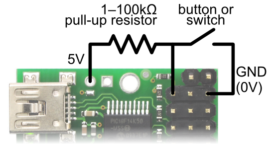 |
Diagram for connecting a button or switch to the Micro Maestro Servo Controller. |
|---|
To connect a button or switch to the Maestro, you must first decide which channel you would like to use. In the Maestro Control Center, under the Channel Settings tab, change that channel to Input mode and click “Apply Settings”. Next, wire a pull-up resistor (1–100 kilo-ohms) between the signal line of that channel and 5 V so that the input is high (5 V) when the switch is open. Wire the button or switch between the signal line and GND (0 V) so that when the button/switch is active the input will fall to 0 V. The picture to the right shows how to connect a button or switch to channel 0 on the Micro Maestro 6-channel servo controller.
Note: An external pull-up resistor is not needed if you use channel 18, 19, or 20 on the Mini Maestro 24-channel servo controller and enable its internal pull-up resistor in Channel Settings tab of the Maestro Control Center.
You can test your input by toggling the button/switch and verifying that the “Position” variable as shown in the Status tab of the Maestro Control Center reflects the state of your button/switch: it should be close to 255.75 when the button/switch is inactive and close to 0 when it is active. Now you can read the state of the button/switch in your script using the GET_POSITION command or over serial using the “Get Position” command. These commands will return values that are close to 1023 when the button/switch is inactive and close to 0 when it is active.
Potentiometer
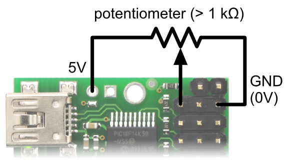 |
Diagram for connecting a potentiometer to the Micro Maestro servo controller. |
|---|
To connect a potentiometer to the Maestro, you must first decide which channel you would like to use. If you have the Mini Maestro 18- or 24-channel servo controller, be sure to pick one of the analog input capable channels (channels 0–11). In the Maestro Control Center, under the Channel Settings tab, change that channel to Input mode and click “Apply Settings”. Next, connect the potentiometer to the Maestro so that the two ends go to GND and 5 V, and the wiper connects to the signal line of the channel. The picture to the right shows how to connect a potentiometer to channel 0 on the Micro Maestro 6-channel servo controller. The potentiometer should have a resistance of at least 1 kilo-ohm so that it does not draw too much current from the 5V line.
You can test your input by rotating the potentiometer and verifying that the “Position” variable as shown in the Status tab of the Maestro Control Center reflects the position of the potentiometer: it should vary between approximately 255.75 and 0. Now you can read the position of the potentiometer in your script using the GET_POSITION command or over serial using the “Get Position” command. These commands will return values between approximately 1023 and 0.
LED
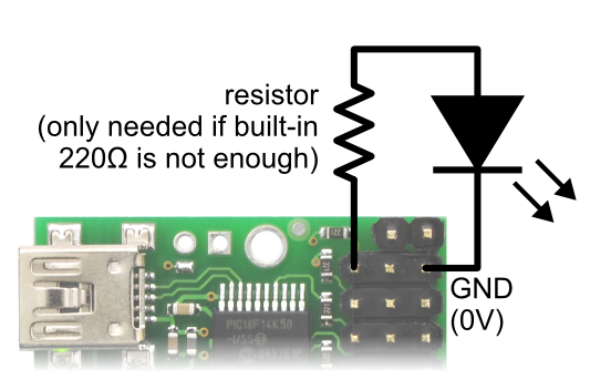 |
Diagram for connecting an LED to the Micro Maestro servo controller. |
|---|
To connect an LED to the Maestro, you should first decide which channel you would like to use. In the Maestro Control Center, under the Channel Settings tab, change that channel to Output mode and click “Apply Settings”. Next, connect the cathode of the LED to GND (any ground pad on the Maestro will suffice because they are all connected). Then connect the anode of the LED to the channel’s signal line (through a resistor is needed). The signal line has a 220 ohm resistor for protection, which means you can connect most LEDs directly to the signal line. However, you should read your LED’s datasheet to make sure, and add your own resistor if needed.
You can test your LED by setting the “target” of the LED channel in the Status tab of the Maestro Control Center. The LED should be on if you set the target to be greater than or equal to 1500 μs and off otherwise. You can control the LED in your script using the SERVO command or over serial using the “Set Target” command. These commands take arguments in units of quarter-microseconds, so the LED should be on if you send a number greater than or equal to 6000 and off otherwise.
Related products


Home | Forum | Blog | Support | Ordering Information | Wish Lists | Distributors | BIG Order Form | About | Contact
© 2001–2024 Pololu Corporation
