Support » Pololu Jrk USB Motor Controller User’s Guide » 1. Overview »
1.a. Module Pinout and Components
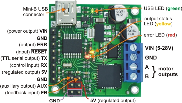 |
Pololu Jrk 21v3 USB motor controller with feedback, labeled top view. |
|---|
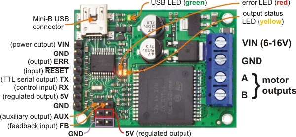 |
Pololu Jrk 12v12 USB motor controller with feedback, labeled top view. |
|---|
The Pololu jrk USB motor controller can connect to a computer’s USB port via a USB A to mini-B cable (not included). The USB connection is used to configure the motor controller. It can also be used to send commands to the motor controller, get information about the motor controller’s current state, and send and receive TTL serial bytes on the TX and RX lines.
Power for the motor must be supplied to the jrk on the VIN and GND lines pictured on the right side of the diagram above. Your power source must be capable of delivering the current your motor will draw. The jrk has reverse power protection on the motor power input lines, so the board will not be damaged if the motor power inputs are accidentally switched. If the VIN supply is not present, the jrk’s microcontroller can be powered directly from USB and perform all of its functions except for driving the motor.
For the jrk 21v3, the input voltage should be 5–28 V (the recommended operating voltage is 8–28 V, but the jrk 21v3’s motor driver has derated performance down to 5 V and transient protection to 40 V). The jrk 21v3’s motor driver can supply a continuous 3 A with peaks up to 5 A.
For the jrk 12v12, the input voltage should be 6–16 V. The jrk 12v12’s motor driver can supply a continuous 12 A with peaks up to 30 A.
The jrk has a linear voltage regulator that derives 5 V from the VIN supply. The 5 V supply is used as the internal logic supply for the jrk and is also available at several pins for powering devices such as external microcontrollers and feedback sensors (such as potentiometers). Because the regulator must dissipate excess power as heat, the available output current is dependent on the input voltage: 50 mA is available for VIN up to 12 V; the available current drops off linearly from 50 mA at 12 V to zero at 30 V.
The jrk has three indicator LEDs:
- The green USB LED indicates the USB status of the device. When the jrk is not connected to a computer via the USB cable, the green LED will be off. When you connect the jrk to USB, the green LED will start blinking slowly. The blinking continues until the jrk receives a particular message from the computer indicating that the jrk’s USB drivers are installed correctly. After the jrk gets this message, the green LED will be on, but it will flicker briefly when there is USB activity. The configuration utility constantly streams data from the jrk, so when the configuration utility is running and connected to the jrk, the green LED will flicker constantly.
- The red error LED indicates an error. If there is an error stopping the motor (besides the Awaiting Command error bit), then the red LED will be on. The red LED is tied to the active-high output ERR, so when there is an error, ERR will be driven high, and otherwise it will be pulled low through the LED.
- The yellow output status LED indicates the status of the motor. If the yellow LED is off, then an error (other than the Awaiting Command error bit) is stopping the motor. If the yellow LED is flashing slowly (once per second), then either the motor is off (the Awaiting Command Error bit is set) or the jrk is in speed control mode and the duty cycle is zero. If the yellow LED is on solid, then the motor is on and the motor has reached the desired state. For analog and pulse width feedback modes, this means that the target is within 20 of the scaled feedback. For speed control mode, this means that the duty cycle equals the duty cycle target. If the yellow LED is flashing quickly (16 times per second), then the motor is on and the motor has not reached its desired state.
The ERR line is an optional output that is tied to the red error LED described above. It is driven high when the red LED is on, and it is a pulled low through the red LED when the red LED is off. Since the ERR line is never driven low, it is safe to connect the ERR line of multiple jrks together. Please note, however, that doing this will cause the error LEDs of all connected jrks to turn on whenever one jrk experiences an error; the ERR output of the jrk experiencing the error will drive the LEDs of any other jrks it is connected to, even though they are not experiencing error conditions themselves. For more information on the possible error conditions and response options, please see Section 3.f.
The TX line transmits non-inverted, TTL (0 – 5 V) serial bytes. These bytes can either be responses to serial commands sent to the jrk, or arbitrary bytes sent from the computer via the USB connection. For more information about the jrk’s serial interface, see Section 4.
The RX line is the jrk’s control input. In serial input mode, the RX line is used to receive non-inverted, TTL (0 – 5 V) serial bytes. These bytes can either be serial commands for the jrk, arbitrary bytes to send back to the computer via the USB connection, or both. For more information about the jrk’s serial interface, see Section 4. In analog input mode, RX is the analog input line used to determine the system’s target output. In pulse width input mode, the jrk measures the duration of pulses on the RX line to determine the system’s target output. Please see Section 3.b for more information on control input signals.
The FB line is the jrk’s feedback input. In analog feedback mode, the voltage on the FB line is used as a measurement of the output of the system. In frequency feedback mode, the frequency of low-to-high transitions on the FB line is used as a measurement of the output of the system. Please see Section 3.c for more information on feedback signals.
The AUX line is an output that is generally high whenever the jrk has power. The line will only go low for two reasons:
- If the jrk’s microcontroller goes to sleep (because there is no VIN supply and the device has entered USB suspend mode), the pin is tri-stated and pulled low through a resistor.
- If the Detect disconnect with AUX option is enabled for either the feedback or the input, then the jrk will drive AUX low for about 150 μs each PID period to check if the feedback and/or analog inputs are disconnected.
The RST pin can be driven low to perform a hard reset of the jrk’s microcontroller, but this should generally not be necessary for typical applications. The line is internally pulled high, so it is safe to leave this pin unconnected.


Home | Forum | Blog | Support | Ordering Information | Wish Lists | Distributors | BIG Order Form | About | Contact
© 2001–2024 Pololu Corporation
