Support » Pololu 3pi Robot User’s Guide »
9. Pin Assignment Tables
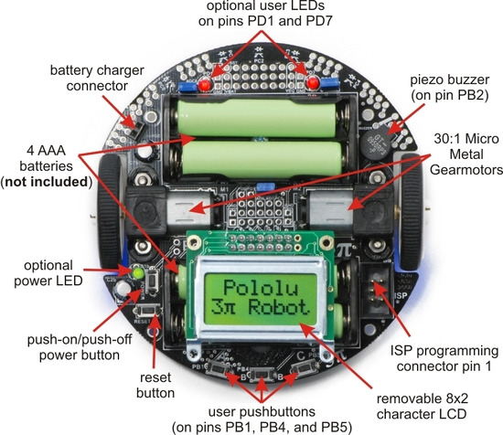 |
General features of the Pololu 3pi robot, top view. |
|---|
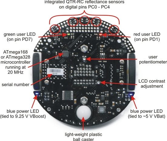 |
Labeled bottom view of the Pololu 3pi robot. |
|---|
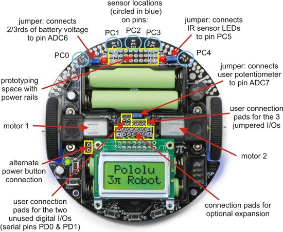 |
Specific features of the Pololu 3pi robot, top view. |
|---|
Pin Assignment Table Sorted by Function
| Function | ATmegaxx8 Pin | Arduino Pin |
|---|---|---|
| free digital I/Os (x3) (remove PC5 jumper to free digital pin 19) | PD0, PD1, PC5 | digital pins 0, 1, 19 |
| free analog inputs (if you remove jumpers, x3) | PC5, ADC6, ADC7 | analog inputs 5 – 7 |
| motor 1 (left motor) control (A and B) | PD5 and PD6 | digital pins 5 and 6 |
| motor 2 (right motor) control (A and B) | PD3 and PB3 | digital pins 3 and 11 |
| QTR-RC reflectance sensors (left to right, x5) | PC0 – PC4 | digital pins 14 – 18 |
| red (left) user LED | PD1 | digital pin 1 |
| green (right) user LED | PD7 | digital pin 7 |
| user pushbuttons (left to right, x3) | PB1, PB4, and PB5 | digital inputs 9, 12, and 13 |
| buzzer | PB2 | digital pin 10 |
| LCD control (RS, R/W, E) | PD2, PB0, and PD4 | digital pins 2, 8, and 4 |
| LCD data (4-bit: DB4 – DB7) | PB1, PB4, PB5, and PD7 | digital pins 9, 12, 13, and 7 |
| reflectance sensor IR LED control (drive low to turn IR LEDs off) | PC5 (through jumper) | digital pin 19 |
| user trimmer potentiometer | ADC7 (through jumper) | analog input 7 |
| 2/3rds of battery voltage | ADC6 (through jumper) | analog input 6 |
| ICSP programming lines (x3) | PB3, PB4, PB5 | digital pins 11, 12, and 13 |
| reset pushbutton | PC6 | reset |
| UART (RX and TX) | PD0 and PD1 | digital pins 0 and 1 |
| I2C/TWI | inaccessable to user | |
| SPI | inaccessable to user | |
Pin Assignment Table Sorted by Pin
| ATmegaxx8 Pin | 3pi Function | Notes/Alternate Functions |
|---|---|---|
| PD0 | free digital I/O | USART input pin (RXD) |
| PD1 | free digital I/O | connected to red user LED (high turns LED on) USART output pin (TXD) |
| PD2 | LCD control line RS | external interrupt 0 (INT0) |
| PD3 | M2 control line | Timer2 PWM output B (OC2B) |
| PD4 | LCD control line E | USART external clock input/output (XCK) Timer0 external counter (T0) |
| PD5 | M1 control line | Timer0 PWM output B (OC0B) |
| PD6 | M1 control line | Timer0 PWM output A (OC0A) |
| PD7 | LCD data line DB7 | connected to green user LED (high turns LED on) |
| PB0 | LCD control line R/W | Timer1 input capture (ICP1) divided system clock output (CLK0) |
| PB1 | LCD data line DB4 | user pushbutton (pressing pulls pin low) Timer1 PWM output A (OC1A) |
| PB2 | buzzer | Timer1 PWM output B (OC1B) |
| PB3 | M2 control line | Timer2 PWM output A (OC2A) ISP programming line |
| PB4 | LCD data line DB5 | user pushbutton (pressing pulls pin low) Caution: also an ISP programming line |
| PB5 | LCD data line DB6 | user pushbutton (pressing pulls pin low) Caution: also an ISP programming line |
| PC0 | QTR-RC reflectance sensor | (drive high for 10 us, then wait for line input to go low) sensor labeled PC0 (leftmost sensor) |
| PC1 | QTR-RC reflectance sensor | (drive high for 10 us, then wait for line input to go low) sensor labeled PC1 |
| PC2 | QTR-RC reflectance sensor | (drive high for 10 us, then wait for line input to go low) sensor labeled PC2 (center sensor) |
| PC3 | QTR-RC reflectance sensor | (drive high for 10 us, then wait for line input to go low) sensor labeled PC3 |
| PC4 | QTR-RC reflectance sensor | (drive high for 10 us, then wait for line input to go low) sensor labeled PC4 (rightmost sensor) |
| PC5 | analog input and digital I/O | jumpered to sensors’ IR LEDs (driving low turns off emitters) ADC input channel 5 (ADC5) |
| ADC6 | dedicated analog input | jumpered to 2/3rds of battery voltage ADC input channel 6 (ADC6) |
| ADC7 | dedicated analog input | jumpered to user trimmer potentiometer ADC input channel 7 (ADC7) |
| reset | reset pushbutton | internally pulled high; active low digital I/O disabled by default |


Home | Forum | Blog | Support | Ordering Information | Lists | Distributors | BIG Order Form | About | Contact
© 2001–2026 Pololu Corporation
