Support » Pololu Baby Orangutan B User’s Guide »
4. Module Pinout and Component Identification
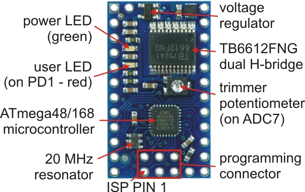
The Baby Orangutan contains a programmable ATmega48, ATmega168, or ATmega328P AVR microcontroller, a TB6612FNG dual H-bridge for direct control of two DC motors, a 10k user trimmer potentiometer (connected to ADC7), a green power LED, a red user LED (connected to PD1), a 20 MHz resonator, and a reverse-battery-protection MOSFET, all containted in a tiny 1.2" x 0.7" 24-pin DIP package. Power pins, one of the motor outputs, and several I/O lines are all accessible from one side to enable use of the Baby Orangutan as a single in-line pin (SIP) package for applications that do not require all of the I/O lines.
|
|
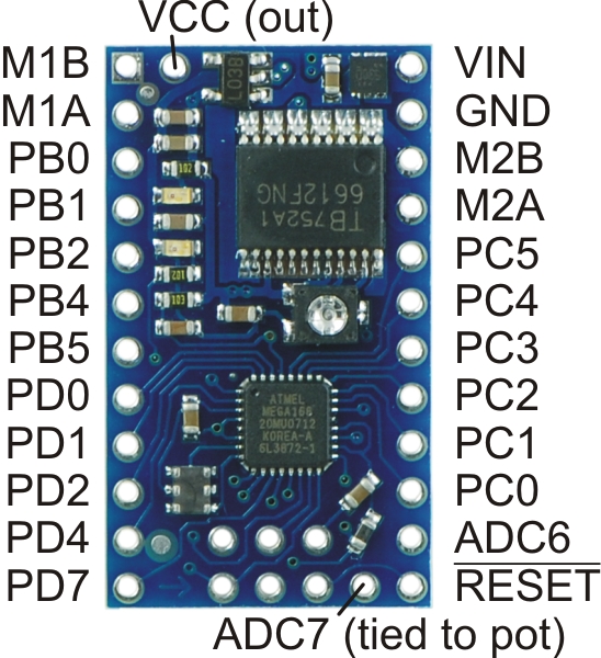
The pinout diagram, combined with a pin assignment table, is also available as a downloadable pdf: Baby Orangutan B pinout and pin assignment table (285k pdf).
- VIN should be from 5 to 13.5 V, with an absolute maximum of 15 V.
- RESET can be brought low to reset the controller, but it can otherwise be left disconnected (it is internally pulled high). This pin is labeled as PC6 in the ATmega48/168/328 datasheet (and on the Baby Orangutan silkscreen).
- Vcc can be used to tap into the Baby Orangutan’s regulated 5V line. This line can supply a total of around 100 mA at 5 V, but thermal dissipation limits the total Vcc current to around 50 mA at 13.5 V. Note that attempting to pull too much current from Vcc could permanently damage the Baby Orangutan’s voltage regulator.
- M1A & M1B are the outputs used to drive motor 1. These outputs can supply around 1 A continuous (3 peak).
- M2A & M2B are the outputs used to drive motor 2. These outputs can supply around 1 A continuous (3 peak).
- PC0 – PC5 can be used as both analog inputs and digital I/O lines
- ADC6 & ADC7 are dedicated analog inputs. Note that ADC7 is internally connected to the 10k user trimmer potentiometer.
- PB0, PB3, PB4, PB5, PD0, PD1, PD2, PD3, PD4, & PD7 are digital I/O lines with alternate functions determined by the AVR hardware peripherals to which they connect. For example, PD0 and PD1 connect to the ATmega48/168’s UART and can be configured to function as RX and TX, respectively. Note that PD1 is internally connected to the red user LED, which may limit its ability to be used as an input (if the source cannot drive the PD1 hard enough, the voltage will be pulled below the AVR’s high threshold by the LED-resistor circuit ).
Warning: Pins PB4 and PB5 are used as ISP programming pins in addition to digital user I/O lines. Be careful not to connect anything to these pins that might interfere with programming (e.g. large capacitance or an external device that could drive those lines during programming). Similarly, don’t connect anything to those lines that might behave unexpectedly when they are driven during programming (e.g. if you use these lines as inputs to a motor driver IC, it could drive your motors in strange and potentially dangerous ways during programming) .
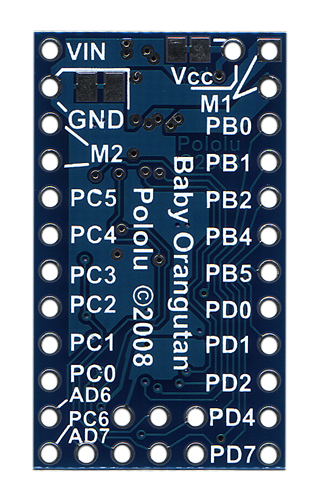
You can tap into the Baby Orangutan’s regulated 5V Vcc line using the pin labeled “Vcc” or either of the two pads on the bottom of the board directly to the left of this pin. You can tap into the Baby Orangutan’s ground using the two pads on the bottom of the board directly to the right of the “GND” pin.
 |


Home | Forum | Blog | Support | Ordering Information | Wish Lists | Distributors | BIG Order Form | About | Contact
© 2001–2024 Pololu Corporation
