Support » QTR-8A and QTR-8RC Reflectance Sensor Array User’s Guide »
5. Module Connections
The QTR-8x reflectance sensor arrays are designed to provide some connection flexibility. The pins are standard 0.1" spacing and are arranged to support connection using either an 11×1 header strip or an 8×2 header strip. A 25-pin 0.1" header strip is included with the module; you can break this strip into smaller strips and solder them as desired, or you can solder wires directly to the unit for a more compact installation. The two connection methods are pictured below:
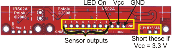 |
QTR-8x reflectance sensor array with 11×1 connection pins labeled. |
|---|
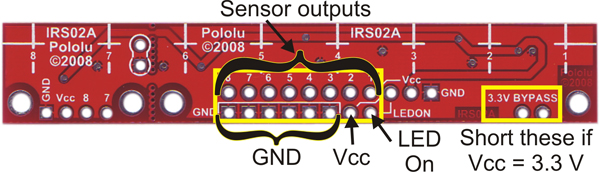 |
QTR-8x reflectance sensor array with 8×2 connection pins labeled. |
|---|
Several pins appear in multiple locations, but you can leave duplicate connection points disconnected. For example, you do not need to connect ground to all six ground pins along the lower edge of the board. Duplicate pins exist so that you can choose the most convenient points to make your connections.
Vcc, GND, and 3.3V BYPASS
The Vcc and GND pins are where the sensor array receives its power. Your Vcc connection must be between 3.3 and 5 V and must be able to supply at least 100 mA. The sensor’s outputs will be relative to GND.
The module is calibrated so that its IR LEDs will achieve optimal brightness when Vcc is 5 V; using a lower Vcc will decrease the LED brightness or cause them to turn off completely. You can compensate for this by shorting the two 3.3V BYPASS pins together, which bypasses one stage of the LED current-limiting resistors and increases LED brightness.
Note: Do not short the 3.3V BYPASS pins together while using a Vcc of 5 V. While this would make the LEDs even brighter, it would exceed their current rating and put them at risk of burning out.
LEDON
This pin is connected to a MOSFET that delivers power to the IR LEDs, so its state determines the whether the LEDs are on or off. When this pin is driven high or left disconnected (it is internally pulled high), the LEDs are all on; when this pin is driven low, the LEDs are off. You can use this pin to save power by turning the LEDs off while you are not taking a reading. Additionally, you can connect this pin to a high-frequency PWM to control effective LED brightness and decrease power consumption.
QTR-8A Sensor Outputs
The QTR-8A reflectance sensor array has eight distinct sensor outputs, one from each LED/phototransistor pair. These outputs are analog voltages ranging from 0 V to Vcc (which must be between 3.3 and 5 V). With a strong reflectance, such as when the sensor is over a white surface, its output voltage will tend towards 0 V; with very weak reflectance, such as when the sensor is over a black surface, its output voltage will tend towards Vcc. To get a good range of readings between white and black surfaces, we recommend you mount your sensor no more than 0.25" away from the surface. In our tests, the optimal distance between the sensor and the surface has been 0.125". Please see our QTR Sample Output Data document for more information.
QTR-8RC Sensor Outputs
The QTR-8RC reflectance sensor array also has eight distinct sensor outputs, one from each LED/phototransistor pair. In the 8RC sensor model, each phototransistor uses a capacitor discharge circuit that allows a digital I/O line on a microcontroller to take an analog reflectance reading by timing how long it takes the output voltage to decay due to the phototransistor. This format has several advantages over the 8A sensor model:
- No analog-to-digital converter (ADC) is required
- Improved sensitivity over voltage-divider analog output
- Parallel reading of all eight sensors is possible with most microcontrollers
- Parallel reading allows optimized use of LED power enable option
When you have a microcontroller digital I/O connected to a sensor output, the typical sequence for reading that sensor is:
- Turn on IR LEDs (optional).
- Set the I/O line to an output and drive it high.
- Allow at least 10 μs for the sensor output to rise.
- Make the I/O line an input (high impedance).
- Measure the time for the voltage to decay by waiting for the I/O line to go low.
- Turn off IR LEDs (optional).
These steps can typically be executed in parallel on multiple I/O lines.
With a strong reflectance, such as when a sensor is over a white surface, the decay time can be as low as several dozen microseconds; with very weak reflectance, such as when the sensor is over a black surface, the decay time will typically be a few milliseconds, but can be several dozen milliseconds in the worst case. The exact time of the decay depends on your microcontroller’s I/O line characteristics. Meaningful results can be available within 1 ms in typical cases (i.e. when not trying to measure subtle differences in low-reflectance scenarios), allowing up to 1 kHz sampling of all 8 sensors. If lower-frequency sampling is sufficient, substantial power savings can be realized by using the LEDON pin to turn off the LEDs. For example, if a 100 Hz sampling rate is acceptable, the LEDs can be off 90% of the time, lowering average current consumption from 100 mA to 10 mA.
If you want to achieve high frequency sampling rates, we recommend you mount your sensors 0.125" away from the surface. The greater your distance from the surface, the lower the overall reflectance will be, which in turn will result in longer decay times. We recommend you mount your sensors no more than 0.375" away from the surface. Please see our Pololu QTR Reflectance Sensor Application Note for more information.
Related products


Home | Forum | Blog | Support | Ordering Information | Wish Lists | Distributors | BIG Order Form | About | Contact
© 2001–2024 Pololu Corporation
