Support » Pololu TReX User’s Guide » 3. Getting Started »
3.c. Jumper Settings
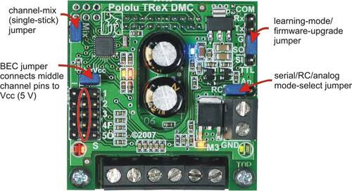
The TReX comes with four blue shorting blocks as shown in the picture below. These jumpers let you affect some aspects of its behavior without serial configuration commands. Note that we recommend you always power off your TReX before changing jumpers (other than the mix jumper, which can be changed at any time). This is not strictly necessary, but it is the safest practice.
 |
TReX jumpers |
|---|
- Channel-Mix (a.k.a. Single-Stick) Jumper: When this jumper is in place, the TReX operates in single-stick mode. Channel 1 is treated as turn left/right while channel 2 is treated as forward/reverse. When this jumper is off, channel 1 directly controls motor 1 and channel 2 directly controls motor 2. This jumper may be added or removed on the fly.
- Battery Elimination Circuit (BEC, a.k.a. +=Vcc) Jumper: When this jumper is in place, the middle column of channel input pins is connected to Vcc (5 V). You can use this jumper to power your RC receiver or analog controller through your TReX. If your RC receiver is powered via another source, you must leave this jumper off.
Warning: The Vcc column is tied to the output of a linear voltage regulator, so its current output is limited by thermal dissipation. The regulator will only be able to safely supply a maximum of 100 mA when VIN is 16 V (it has a 1-W power dissipation rating). This is typically sufficient for powering an analog joystick or RC receiver, but it is insufficient for powering servos. If you want to connect servos to some of your RC receiver channels, you must power your RC receiver separately and disconnect the BEC jumper. Attempting to use the TReX’s regulated Vcc line to power servos can permanently damage the TReX.
- Mode-Select Jumper: This jumper specifies the interface that is in control of the TReX. When it shorts the left two pins (as shown in the jumper image above), the TReX is in RC mode, which means the TReX is expecting RC pulse inputs on its five input channels and that these RC signals will determine the motor outputs. When the jumper shorts the right two mode pins, the TReX is in analog mode; the TReX measures the analog voltages on the five input channels and sets the motor outputs accordingly. When there is no jumper on the three mode pins, the TReX is in serial mode and the serial interface controls the motors. The control interface is determined by the location of the mode jumper when the TReX is first powered up. Changing the location of the mode jumper while the TReX is running will have no effect.
- Learning-Mode/Firmware-Upgrade Jumper: The TReX can automatically calibrate itself for your RC or analog controller by learning the neutral and extreme values for each channel you use. It also has the ability to upgrade its firmware. When placed across the SO and G pins, this jumper puts the TReX into learning/firmware-upgrade mode via the “secret handshake” (see Section 3.e). The TReX ships with this jumper in place since we recommend your first step be to calibrate for your controller. This jumper should be removed before you begin normal operation.
Warning: You should never add this jumper while the board is powered! Disconnect power from the board, add this jumper, and then reconnect power.


