Pololu Blog »
Pololu Blog (Page 19)
Welcome to the Pololu Blog, where we provide updates about what we and our customers are doing and thinking about. This blog used to be Pololu president Jan Malášek’s Engage Your Brain blog; you can view just those posts here.
Popular tags: community projects new products raspberry pi arduino more…
New product: VL53L1X Time-of-Flight Distance Sensor Carrier

The carrier board for the VL53L1X that many of us have been waiting for is finally here! The VL53L1X is ST’s newest time-of-flight (ToF) range finder for which we first saw announcements over a year ago, but they were not available to us for ordering until earlier this year. The part is pin-compatible with the earlier VL53L0X, so we were able to put them on the same PCB as we use for that carrier as soon as our first reel of new sensors came in.
Be among the first 100 customers to use coupon code VL53L1XINTRO (click to add the coupon code to your cart) and get up to five units at the introductory special price of $8.88 each. We have a few hundred made to begin with, and we are continuing to make more, so even if the available stock goes to zero, you can still backorder with the coupon price and chances are that we will be able to fill your order the same day.
Related products


Video: Overview of the Jrk G2 Motor Controllers with Feedback
In our last blog post, we announced the release of our second generation of Jrk Motor Controllers with Feedback. If that announcement wasn’t enough to get you excited about the Jrks, here’s a short video to give you a taste of what the Jrks can do:
You totally want one now, right? Well lucky for you, our special introductory coupon is still valid. The first 100 customers to use coupon code JRKG2INTRO can get 40% off up to three units. (Click to add the coupon code to your cart.)

New products: Jrk G2 USB Motor Controllers with Feedback
After many months or years of work (depending on how you look at it), I am happy to introduce our newest motor controllers, the Jrk G2 USB Motor Controllers with Feedback, which we are releasing today in four power variants:
 Jrk G2 18v19 |
 Jrk G2 24v13 |
 Jrk G2 18v27 |
 Jrk G2 24v21 |
|
|---|---|---|---|---|
| Recommended max operating voltage: |
24 V(1) | 34 V(2) | 24 V(1) | 34 V(2) |
| Max nominal battery voltage: |
18 V | 28 V | 18 V | 28 V |
| Max continuous current (no additional cooling): |
19 A | 13 A | 27 A | 21 A |
| Dimensions: | 1.4″ × 1.2″ | 1.7″ × 1.2″ | ||
1 30 V absolute max.
2 40 V absolute max.
 |
The main purpose of the Jrk G2 family is to enable feedback-based control of DC brushed motors, simplifying closed-loop control of things like the position of an actuator. An example that is probably familiar to most of us is the common hobby servo that has an output shaft that can rotate to various positions as commanded over a simple interface. The Jrk motor controllers can be used for giant versions of those servos, and they can also be used in many other systems as long as you can somehow get feedback in the form of an analog voltage or a frequency. Analog voltage feedback is often easy to get from potentiometers that can serve as angle or position sensors.
The frequency feedback feature is handy for maintaining a speed of a motor independent of your supply voltage and motor load. You might use that kind of feature to run a treadmill at some set speed independent of the weight of the lab rats on it or to stir some jar of goop at a constant rate as the goop gradually thickens. With mobile robot applications, it can be handy to have a motor controller that will make your wheel go at the speed you set independent of whether the robot is on a hard floor or a carpet. (The Jrks do not support quadrature encoders, but you can use one channel of a quadrature encoder as the tachometer for the Jrk. In some applications, keeping track of absolute position is not necessary, or the quadrature encoder can be monitored directly by a main controller that could still benefit from the closed-loop speed control being taken care of by the motor controller.)
To control a wide range of motors in a variety of applications, it’s important to be able to configure a lot of parameters, which makes the Jrk’s USB connection and free configuration utility software extremely important. Even if you ultimately want to use your Jrk in a radio control installation or command it over I²C from your favorite embedded controller, it’s very convenient to be able to set everything up from your computer.
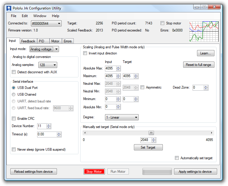 |
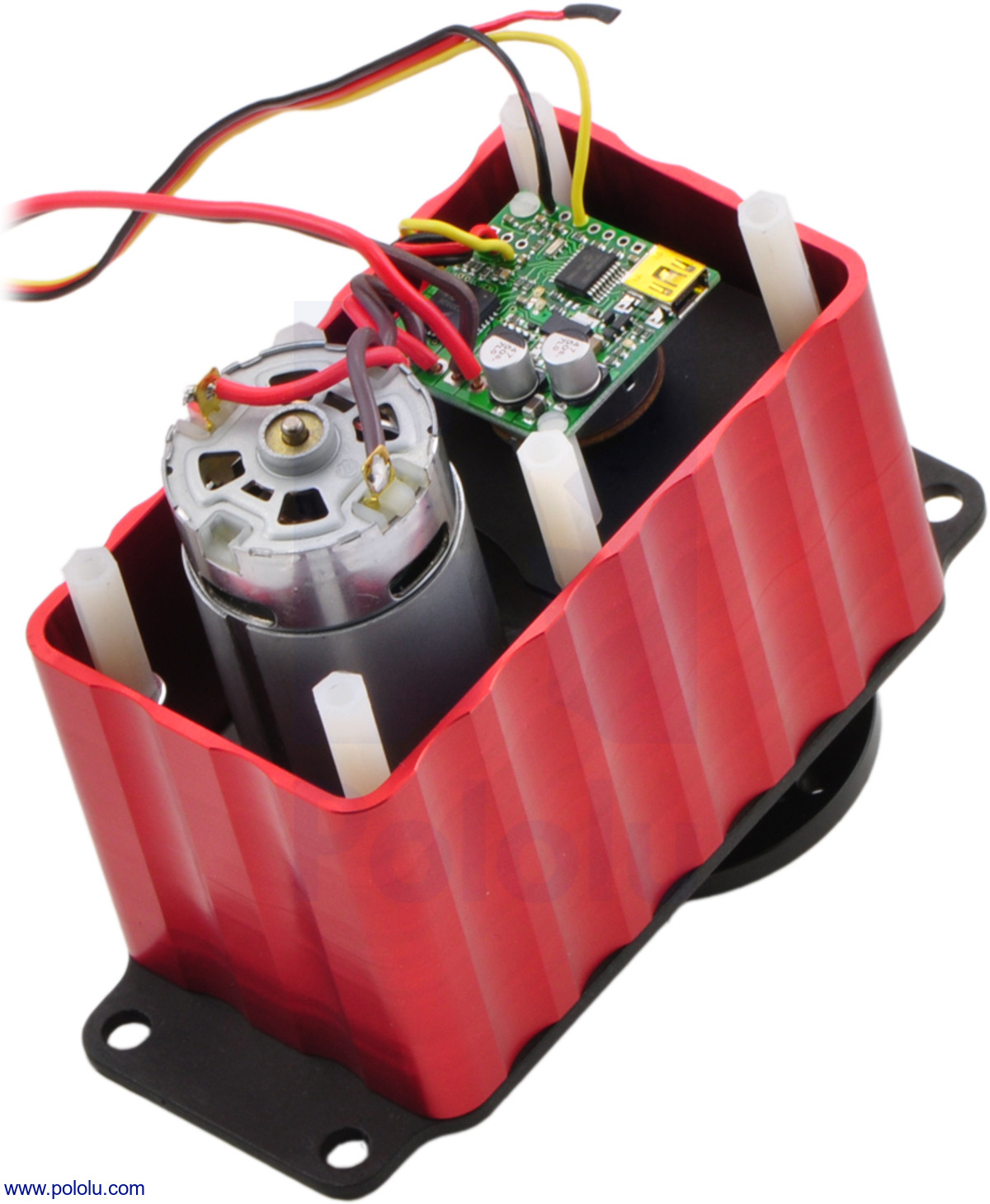
That screenshot is actually of the utility for the original Jrks, which we released almost 9 years ago (I announced those on the forum because we did not have this blog back then). You might notice on some older web pages that we referred to the original Jrks as our second-generation feedback controllers. The really original ancestor to today’s new motor controllers is this product we called simply Pololu 3A Motor Controller with Feedback, which we released at the beginning of 2005. Here are a picture and block diagram of that controller:
|
|
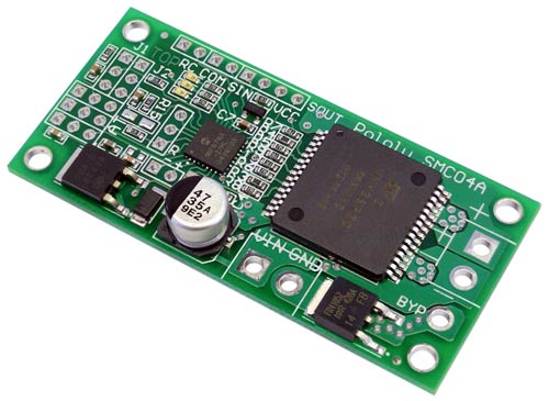 |
Candice and I were probably still running Pololu out of our house back when we started work on that controller, and it’s probably the last product of ours for which Candice wrote some of the firmware. That controller led to the development of a larger, customized controller (similar to our SMC04 High-Power Motor Controller with Feedback) and an even higher-power version that was used on control cables of large autonomous parachutes for the military.
Back to the new Jrk G2 family: these new controllers are in many ways a refinement of the original Jrks, which have been used all over the world in applications from animatronic displays to motion simulators and even full-sized airplanes. The most noticeable improvement on the four Jrk G2 controllers we are releasing today is the increased power available from their discrete MOSFET H-bridges. The G2 high-power motor driver design is part of the reason for the “G2” in the new Jrk family name, though we plan on releasing lower-power, smaller Jrk G2 products later this year. The new driver technology, along with going to double-sided PCB assembly and four-layer PCBs, allowed us to make much higher-power controllers that are smaller than the old Jrk 12v12, which used to be our highest-power version.
The Jrk G2 24v13 and 24v21 in particular open up new application opportunities because they can operate off of 24 V power rails, making them appropriate for huge linear actuators (note that we only carry 12 V versions right now, partly because we did not have controllers that we could recommend for 24 V use). It’s exciting that these tiny boards can control such huge actuators, and the size difference is so big it’s difficult to convey in a picture:
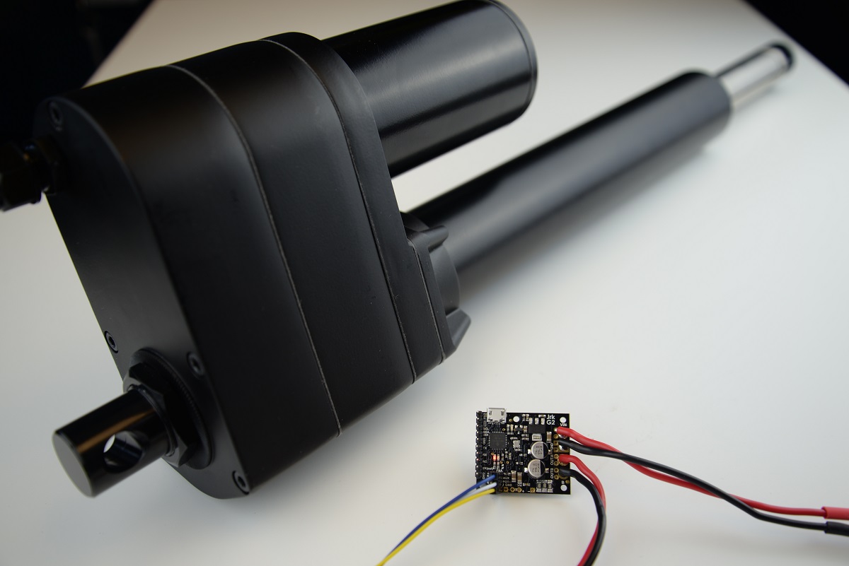 |
The size difference makes it difficult to get a Jrk G2 24v13 and an industrial-duty linear actuator in the same picture. |
|---|
Other features new to the G2 Jrks are an I²C interface option and an improved tachometer/frequency feedback mode that now offers pulse width measuring rather than only frequency counting to allow for better control of low-speed motors with lower-resolution encoders or tachometers. Here is a summary of the main features of the Jrk G2 motor controllers:
- Easy open-loop or closed-loop control of one brushed DC motor
- A variety of control interfaces:
- USB for direct connection to a computer
- TTL serial operating at 5 V for use with a microcontroller
- I²C for use with a microcontroller
- RC hobby servo pulses for use in an RC system
- Analog voltage for use with a potentiometer or analog joystick
- Feedback options:
- Analog voltage (0 V to 5 V), for making a closed-loop servo system
- Frequency pulse counting (for higher-frequency feedback) or pulse timing (for lower-frequency feedback), for closed-loop speed control
- None, for open-loop speed control
- Note: the Jrk does not support using quadrature encoders for position control
- Ultrasonic 20 kHz PWM for quieter operation (can be configured to use 5 kHz instead)
- Simple configuration and calibration over USB with free configuration software utility
- Configurable parameters include:
- PID period and PID constants (feedback tuning parameters)
- Maximum current
- Maximum duty cycle
- Maximum acceleration and deceleration
- Error response
- Input calibration (learning) for analog and RC control
- Optional CRC error detection eliminates communication errors caused by noise or software faults
- Reversed-power protection
- Field-upgradeable firmware
- Optional feedback potentiometer disconnect detection
As with all of our new product releases this year, we are offering an extra introductory discount: the first 100 customers to use coupon code JRKG2INTRO can get 40% off up to three units. (Click to add the coupon code to your cart.)
Related products


Performance graphs for our Micro Metal Gearmotors
|
|
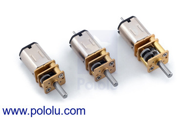
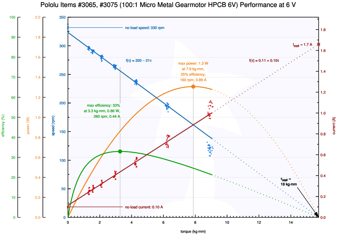
After spending many months conducting thousands of motor tests, we are excited to finally publish performance graphs for our micro metal gearmotors (5MB pdf). In some sense, this datasheet is the culmination of a decade of work to improve our processes and better characterize our gearmotors, and we have come a long way since those early tests clamping motors in vises and making them lift ever heavier bags of steel bearings. Here is one of the setups we are using now:
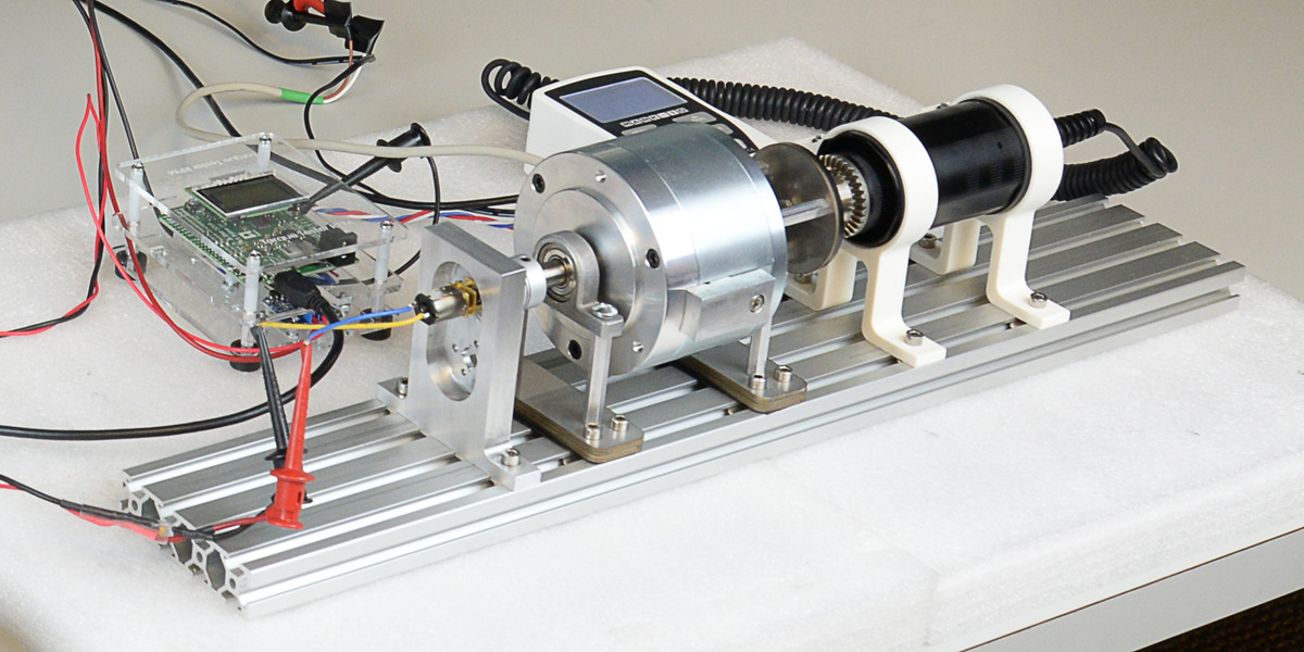 |
Micro Metal Gearmotor undergoing dynamic performance testing. |
|---|
The key thing is to be able to apply a measurable, variable load while the motor is spinning, which we do via an electromagnetic brake coupled to a torque meter. A combination of programs running on an A-Star 32U4 Prime test controller and a PC automatically sweep the load through a sequence of points while measuring parameters such as speed, current, and torque (plus internal test rig currents, voltages, etc).
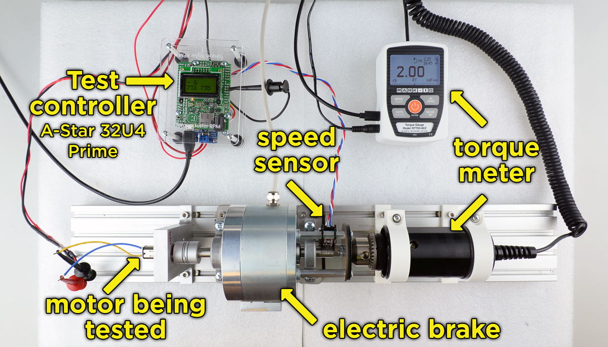 |
Micro Metal Gearmotor performance test setup. |
|---|
These performance characterizations are the latest example of our continued commitment to being the best source for this popular form factor of gearmotor. You might see similar-looking motors elsewhere, but no one comes close to our offering, from the quality of the gears to our exclusive long-life carbon brush options to the overall breadth of our selection (over 100 versions!), all in stock for shipment the day you order.
Please note that we are still in the process of updating the specifications on our website to match new, more accurate data from the performance graphs, so if you notice discrepancies between what is in the datasheet and what is on the product page, go with the datasheet.
If you have any questions or feedback about these graphs or if there is additional information you would like to see available for our motors, please feel free to contact us (or just leave a comment below). And if you are wondering about graphs for our larger gearmotors, don’t worry, those are coming! (If you need something before those datasheets are done, just let us know and we might be able to get you preliminary data for a particular gearmotor.)
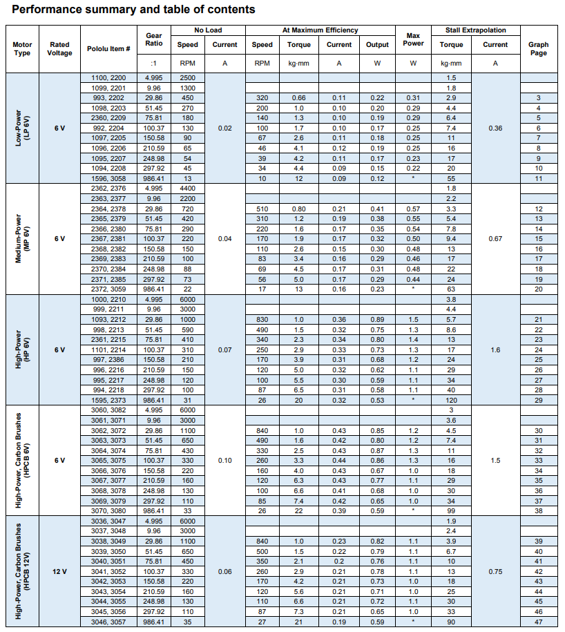 |
Performance summary table from Micro Metal Geamotor datasheet. |
|---|
UNLV wins 1st place in Student Design Competition at ASME E-Fest West
 |
At Pololu, I have spent the recent weeks developing new products, like the motor driver I announced on Wednesday, but at school (I am a mechanical engineering student at the University of Nevada, Las Vegas, UNLV) I have been managing an American Society of Mechanical Engineers (ASME) Student Design Competition (SDC) team. SDC teams create robotic devices to fulfill a problem statement that changes every year. They compete with their devices at one of ASME’s regional student conferences called E-Fests. Last year, I managed a three-member team that built The Rebel WIP and earned third place in the Robot Pentathalon at the E-Fest West. This year, my ten-member team made a squad of robots called The Rebel Bandits for the new SDC challenge, Robot Football. We overcame many technical challenges and 14 other teams to win first place at this year’s E-Fest West that competed this past Saturday!
The SDC’s Robot Football was loosely based on soccer, but with four robot teams competing to shoot eight tennis balls into four goals on a 5 m x 5 m field. Each team was assigned a goal to defend, and eight tennis balls were set in a square pattern at the center of the field for robots to score into the other goals. For this competition, teams could build multiple remote controlled robots, but the robots and controllers had to be able to fit inside a single 50 cm cube. Some teams built soccer squads with only two or three big robots, while other teams used up to six little robots for their squad (which made the matches super chaotic), but each team could only control one ball at a time. Robots controlling a ball needed to keep the ball on the ground when they moved around, but they could stop and lift the ball to shoot on a goal.
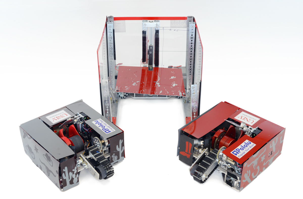 |
The Rebel Bandits. |
|---|
 |
The Outlaw. |
|---|
I am really proud of the robots my team designed and built for this competition, so I want to share how my team made a first place robot squad! However, since we won the competition at E-Fest West, we were invited to compete again in the SDC Finals at ASME’s International Mechanical Engineering Congress and Exposition in Pittsburgh, Pennsylvania this November. We will be competing against the first and second place winners from the other student conferences: E-Fest East, E-Fest Asia Pacific, and E-Fest South America, as well as the SDC team from California State University, Northridge, who came in second place at E-Fest West. The teams will be more competitive, and the prize money increases significantly! So that makes me a little bit nervous about showing all the technical details for our robots right now, but I would still like to give a basic rundown.
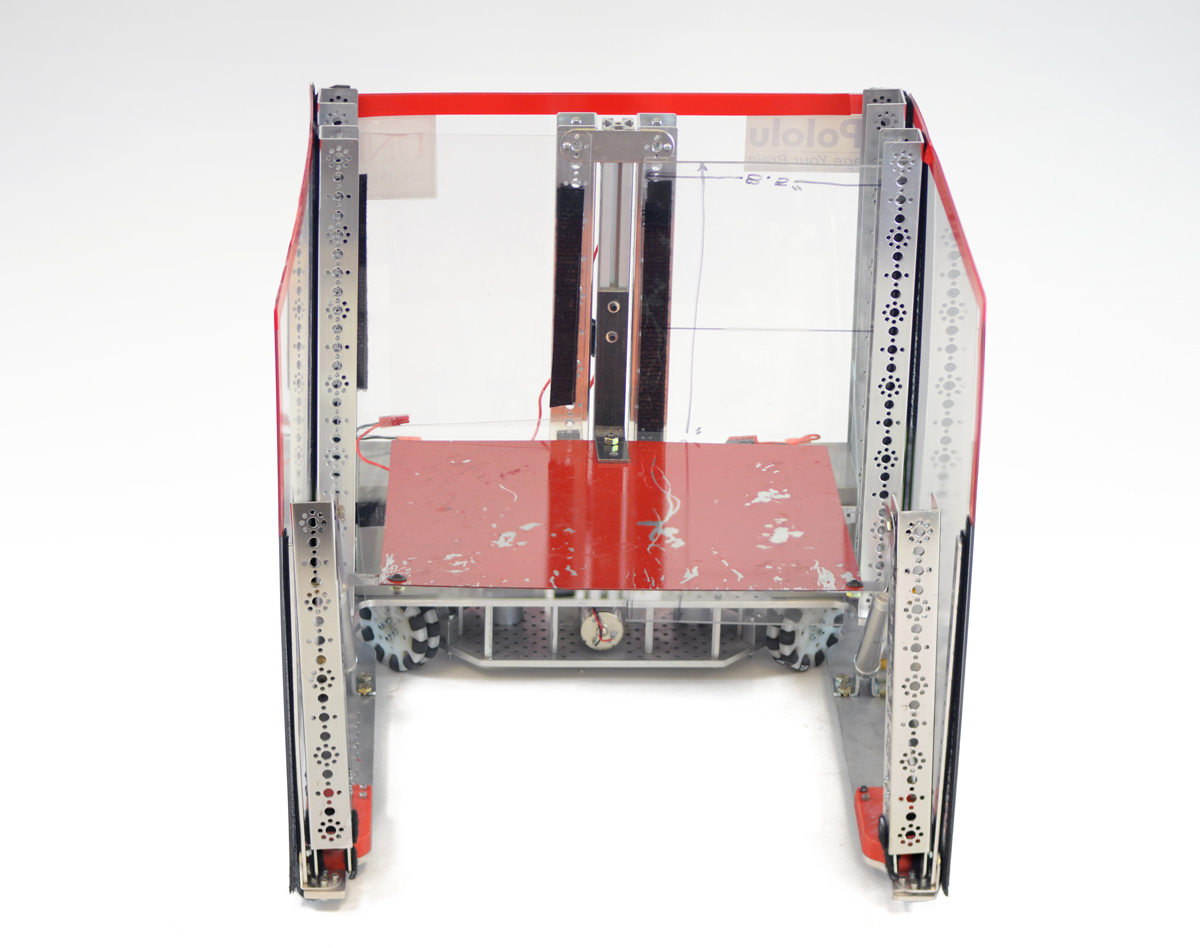
Our strategy was to build three large robots: one defender, and two offensive robots. We call the defender robot The Outlaw. It is built on a U-shaped frame with 19 in (48.3 cm) long sides and has tall walls. Even though it cannot block from inside our penalty box and is not particularly fast, it can seriously impede the efforts of other teams to score on our goal just by being big and tall. The Outlaw uses three DC motors for its drive train at the base of the U-frame, and Pololu ball casters help support the far ends of the U-frame. One DC motor is driven by a G2 High-Power Motor Driver, and since we use an A-Star 32U4 SV for the Outlaw’s microcontroller, the other two DC motors are driven by a Dual G2 High-Power Motor Driver Shield for Arduino.
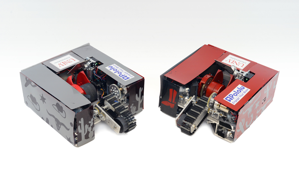 |
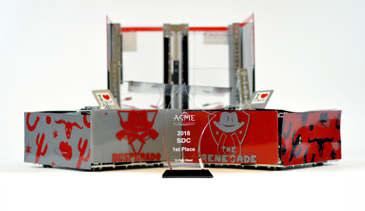
The Desperado and The Renegade. |
|---|
The two offensive robots are named The Renegade and The Desperado (you should notice the Wild West theme by now). Other than the color schemes, these robots are almost complete duplicates. We decided to build only two offensive robots because it gave us sufficient space to build robust robots with high quality shooting mechanisms.
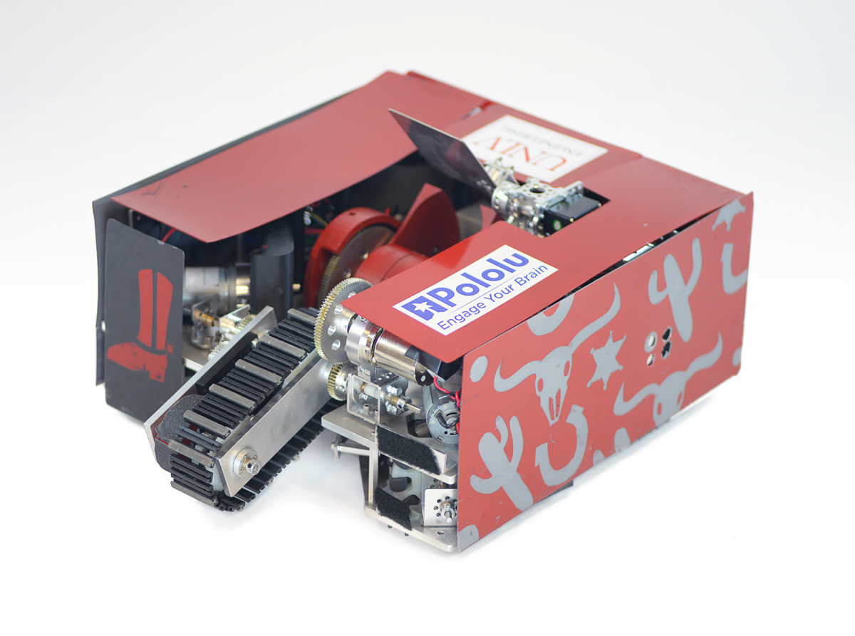 |
Each offensive robot uses four DC motors for the drive train. A standard size servo extends an arm with an intake belt, and a DC motor runs the intake belt to pull a ball into the robot’s reservoir. Another servo opens and closes a gate that keeps the ball in the reservoir or pushes the ball into the shooting mechanism. The reservoir allows the ball to roll on the ground as the robot moves without the intake belt constantly pushing down on the ball and impeding driving. The shooting device is a ramp and flywheel. When taking a shot on the goal, the operator stops the robot and the flywheel revs up to high speed. Then the gate servo pushes the ball into the ramp. The velocity of the wheel pulls the ball along the ramp structure and throws the ball at high velocity. Just beyond the outlet for the ball, a plate on a pivot controlled by a servo lets us control the ball’s trajectory. This allows us to shoot across long distances or over defender robots.
The offensive robots each use an Arduino Mega as their primary microcontroller. Most of the DC motors on The Renegade and The Desperado are controlled by either a Dual G2 High-Power Motor Driver Shield connected to the Arduino Mega or are driven by individual G2 High-Power Motor Drivers. On each robot, a Maestro servo controller is used as a slave controller that powers and controls the standard servos. Additionally we use the Maestros’ functionality as general I/O controllers to send logic signals to the individual 18v17 Motor Drivers. In our setups, we want the servos and the Maestros to be powered from 6 V, so we use a step-down voltage regulator to connect the Maestro power rails to main power supply on each robot, a 12 V lead-acid battery.
I am very fortunate to have worked with an awesome team this year for the SDC, and I am grateful for the parts and support we obtained from both Pololu and UNLV! It was also exciting to see different teams at the competition using other Pololu parts like our wheels, metal gearmotors, regulators, and brushed DC motor drivers. After our SDC Finals competition in November, I plan to write another blog post about more of the technical details of our robot. (Hopefully I will be able to brag a little about another first place trophy too!)
 |
Patrick and 6 members of UNLV’s SDC team that traveled to competition in Pomona, California. |
|---|
Until then, I want to know more about some of your projects! I hope you will share a little about your cool projects in the blog comments, or you can make a Pololu forum account and post in the Share Your Projects category!
Related products


New products: Dual MAX14870 Motor Drivers for Arduino and Raspberry Pi
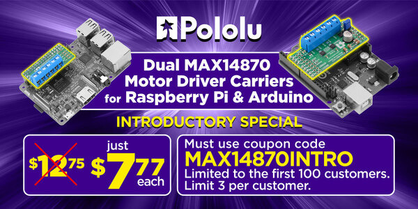
For my birthday, I am excited to share two new products to help get your projects moving: dual motor driver boards for Arduino and for Raspberry Pi based on Maxim MAX14870 drivers, which on these boards (without additional cooling) can power motors with a continuous 1.7 A (2.5 A peak) from a voltage source anywhere from 4.5 V to 36 V. This makes the driver ideal for powering a wide range of motors including our high power micro metal gearmotors, and our 12 V 20D mm metal gearmotors. We like the MAX14870 so much that already we make a single driver carrier for it, and we use it on our A-Star 32U4 Robot Controller SV. These new boards make it easy to control two motors using the MAX14870 with an Arduino or Raspberry Pi.
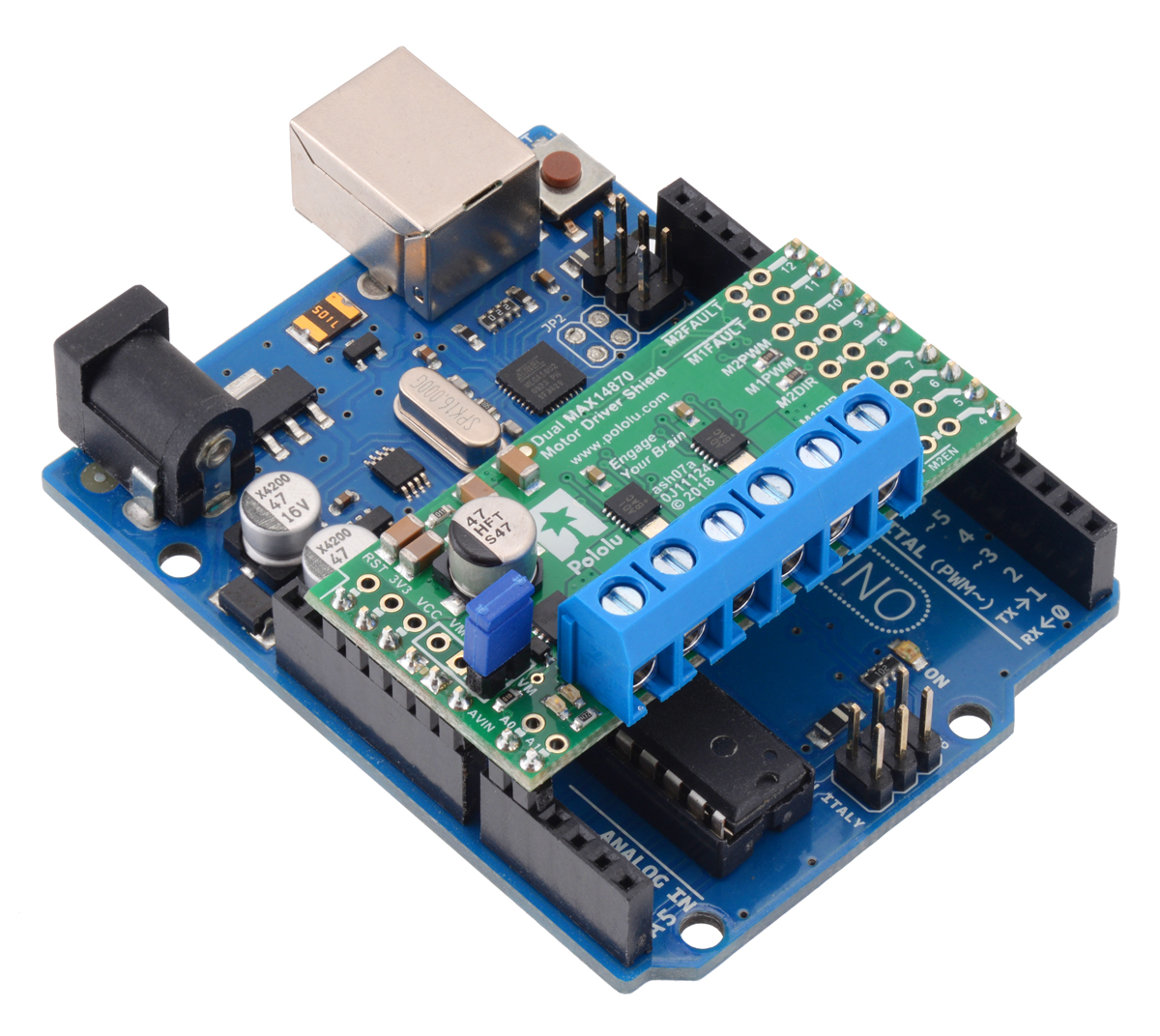 |
The Dual MAX14870 Motor Driver Shield for Arduino is designed to plug directly into an Arduino or another microcontroller board with the Arduino form factor. It connects the Arduino I/O pins to the two-pin speed/direction interfaces as well as the fault output pins, and our open-source library is available to help you get started. The shield can be set up to power your Arduino device from your motor power supply, which is especially helpful if you are using an Arduino or compatible device with an operating voltage similar to that of the MAX14870, such as our A-Star 32U4 Prime SV. Additionally, the board can be customized to use the advanced features of the MAX14870 drivers or change the pin mappings.
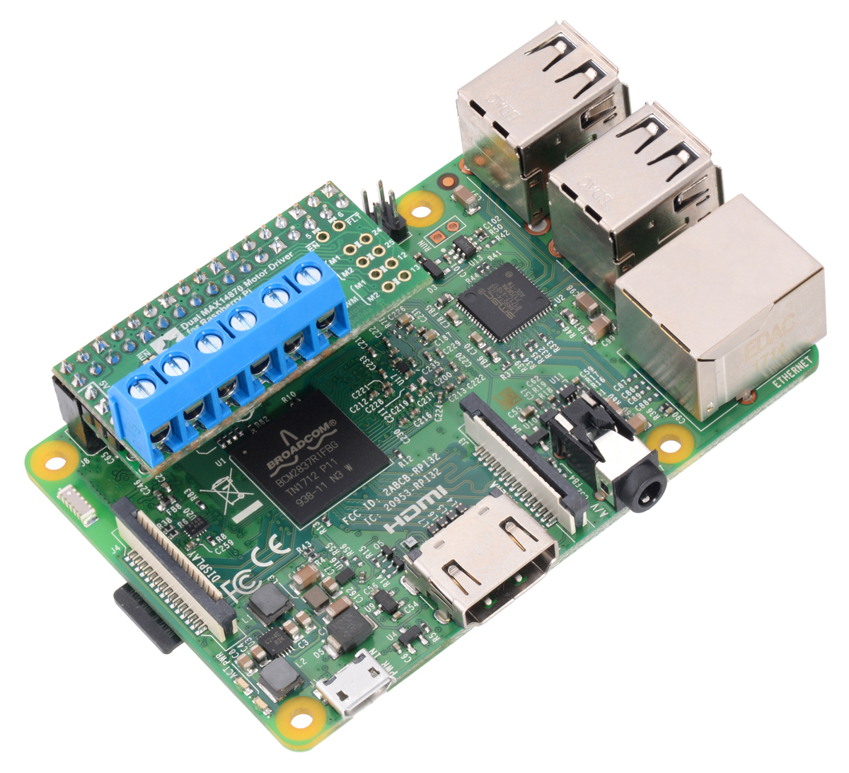
The Dual MAX14870 Motor Driver for Raspberry Pi has many of the same features as the Arduino version, but it is designed to plug into the GPIO header on a compatible Raspberry Pi (Model B+ or newer), including the Pi 3 Model B and Model A+. We provide an open-source Python library to make it easy to interface with the board. This board also has a location to connect a step-down 5 V regulator to power the Raspberry Pi from your motor’s power supply.
|
|

I am really excited about these boards because the Raspberry Pi expansion board is the first PCB I ever designed, and the Arduino shield was designed by my friend David S. Both of us are engineering students at the University of Nevada, Las Vegas who work at Pololu to complement our studies. It has been a great experience for us to learn how to design these products from the development engineers here at Pololu. Plus, getting to share these products for the first time with you is a fun way to celebrate my birthday!
As usual for our new product releases this year, we’re offering an extra introductory discount: the first 100 customers to use coupon code MAX14870INTRO can get any mix of up to 3 of these boards for $7.77 each. (Click to add the coupon code to your cart .) Note that this introductory offer applies only to the units without connectors soldered in.
Related products


Beatty Robotics Curiosity rover replica
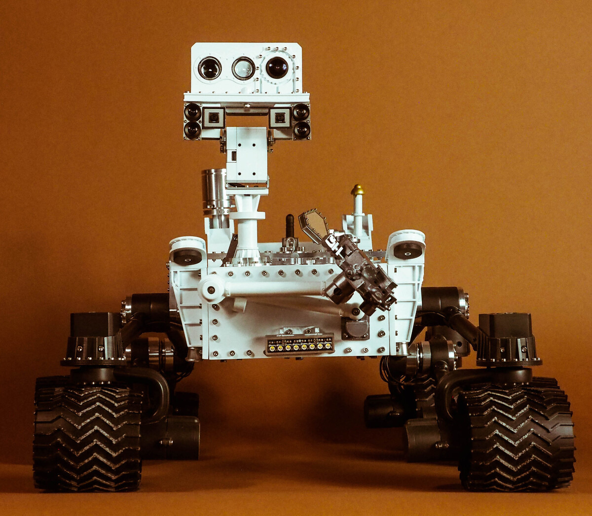 |
Our favorite team of robot-making sisters over at Beatty Robotics has finished making another stellar robot! Their latest creation is a 1/10th scale functional replica of Curiosity, the rover from NASA’s Mars Science Laboratory mission. The rover uses a variety of Pololu products, both mechanical and electrical. For example, it uses a pair of G2 high power motor drivers to control six 25D mm gearmotors, each of which is coupled to a wheel with a 4mm hex adapter. The robot also features our voltage regulators, current sensors, logic level shifters, and pushbutton power switches. In addition to using our products, the rover also uses some stainless steel parts cut with our custom laser cutting service.
The Beattys are currently in the process of documenting their rover. Right now there’s a blog post out focused on the robot’s exterior, but the duo plans to also post about the electronics and functionality soon. We are looking forward to seeing more pictures and learning about how each part contributes to the whole system!
If you are curious to know more about the electronics inside of this replica rover, you can keep an eye on the Beatty website, or you can stay tuned to our blog – we will update you when they share more.
Related products


New product: Pololu USB AVR Programmer v2.1
Our new programmer, the Pololu USB AVR Programmer v2.1, was supposed to be a minor update to our existing programmer, coming right after the A-Star 328PB Micro that we released last month, with the main point of excitement being the Las Vegas-inspired $7.77 price. But as we were testing the combination of the programmer with the A-Star, we were getting brown-out resets on the programmer when it powered the A-Star. The relevant part of the circuit was just a P-channel MOSFET that connected the programmer’s own logic voltage (which we call VDD) to the VCC pin of the ISP connector:
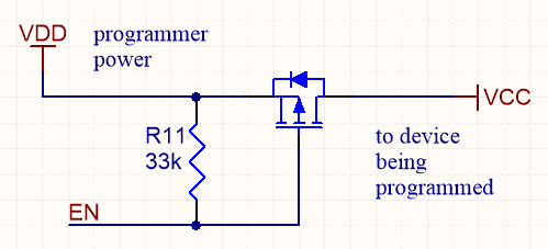 |
MOSFET-based target VCC power control used on Pololu USB AVR Programmer v2. |
|---|
The problem was caused by the MOSFET turning on too well (quickly and with low resistance), causing the logic voltage on the programmer to drop if the VCC of the target device had more than a few µF of discharged capacitance on it. The bigger the capacitance on VCC, the bigger the voltage drop on VDD, until eventually the drop was big enough to trigger the brown-out reset protection on the programmer’s microcontroller. We tried various firmware tricks with our existing hardware, such as turning on the MOSFET for very short pulses to gradually charge up the target device’s VCC capacitance, but none of them worked reliably enough. So in the end, we decided to redo our PCB and put in a dedicated high-side power switch with a controlled slew rate. The new programmer can now power target boards with up to about 33 µF on their logic supplies.
These are the two other improvements we made to the new v2.1 programmer over the older v2 programmer:
 |
- Plugging a v2 programmer into a 3pi robot could cause one of the motors to briefly run at full speed because the programmer’s circuitry for measuring VCC could inadvertently pull up one of the 3pi’s programming pins (which doubles as a motor driver input) before the GND connection was established. The v2.1 programmer has improved circuitry for measuring VCC which limits the duty cycle of this effect to about 0.2%, so the motor won’t move (but it might make a 25 Hz clicking sound).
- The v2 programmer would typically brown-out if a 5 V signal was applied to its RST pin while it was operating at 3.3 V. The v2.1 programmer does not have this problem.
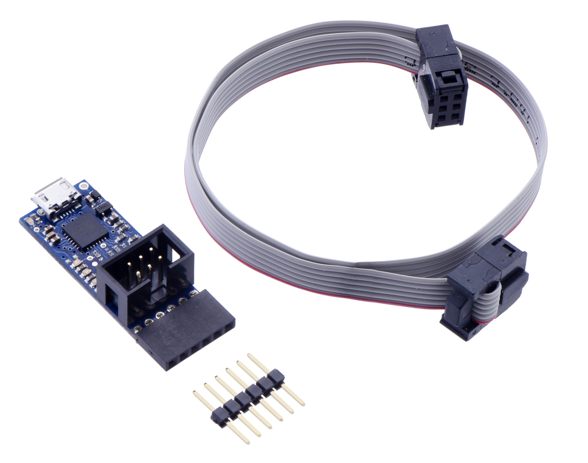
The v2.1 programmer is otherwise identical to the v2 programmer, which means it’s a USB AVR microcontroller programmer that can program targets at 3.3 V and 5 V and offers an extra UART-type TTL serial port (like the popular FTDI USB-to-serial adapters) that can be super handy for debugging, bootloading, or even general connection of your project to a USB port.
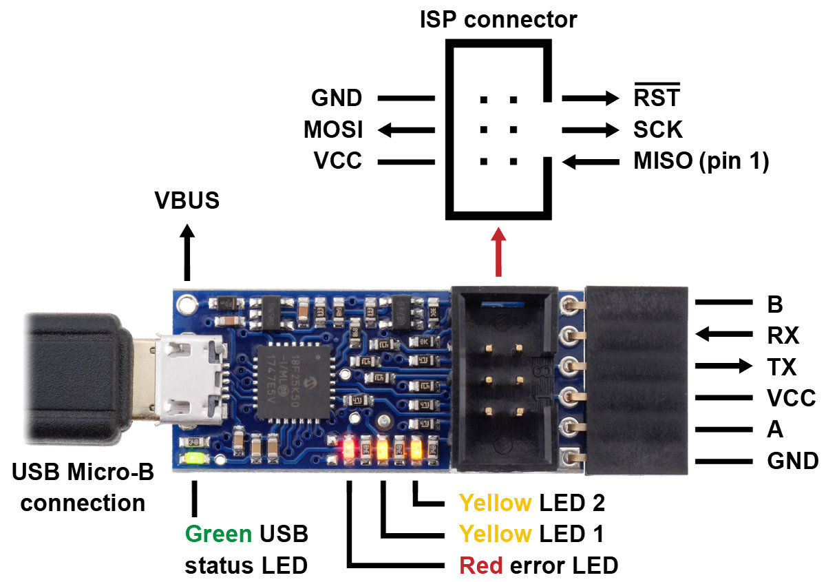 |
Pololu USB AVR Programmer v2.1, labeled top view. |
|---|
The v2 programmer was already a good deal at under $12, but at $7.77, and with free shipping in the USA, we hope to make AVR development extremely accessible. The manufacturing improvements and other cost reduction initiatives I have been blogging about this year help us make this offer without losing money on it, but I am not expecting to be making money directly off of the programmers, either. My goal is to give you the best value in a basic tool you will use over and over as you build your own projects, with the hope that that will help you keep Pololu in mind the next time you need some electronics or robotics parts.
And, as usual for our new product releases this year, we’re offering an extra introductory discount: the first 100 customers to use coupon code AVRPROGINTRO get that already great $7.77 price dropped to $5.55 (limit 2 per customer). (Click to add the coupon code to your cart.)
Related products

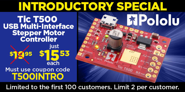
Video: Getting Started with the Tic Stepper Motor Controllers
As I showed in my last post a few weeks ago, our Tic stepper motor controllers offer six different control interfaces so you can add stepper motors to a variety of projects. Getting started with the Tics is easy. This new video tutorial steps (see what I did there?) you through getting your stepper motor running with our Tic controllers:
As I was making this video, I realized one of the coolest things about the Tic is how quickly you can work out the capabilities of your stepper motor. Even if you’re comfortable using one of our stepper motor drivers along with a microcontroller, using the Tics makes adjusting settings like current limits, step rates, speed, and acceleration as quick as a click of the button, and you can control your motor directly from the software to make sure it’s behaving how you would like. So you might want to keep an extra Tic around for that purpose, just as a stepper motor tester.
Right now you can still purchase our newest Tic at a special introductory price of just $15.53 using the coupon code T500INTRO! (Click to add the coupon code to your cart.) We also cover shipping in the US! Note that this introductory offer applies only to the units without connectors soldered in.
Related products


New products: RoboClaw Solo 30A and 60A Motor Controllers
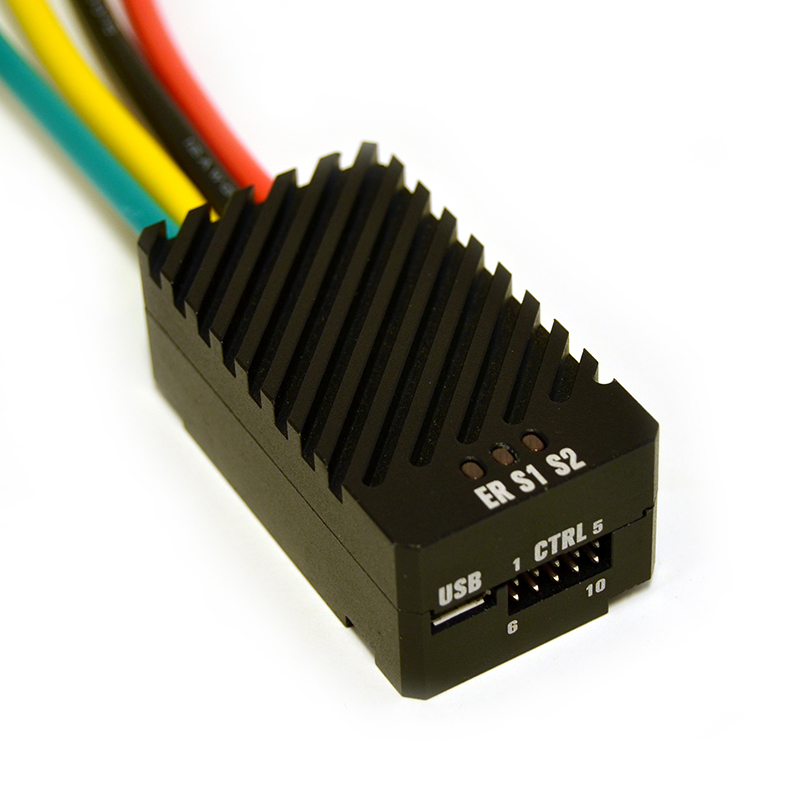 |
We are now carrying Ion Motion Control’s line of single-channel RoboClaws, the Solo 30A and Solo 60A. These versatile, high-power motor controllers have nearly all the same features and performance capabilities as their dual-channel 2×30A and 2×60A counterparts, just with one fewer motor channel. Just like the rest of the RoboClaw family, the Solos support a variety of interfaces, including USB serial, TTL serial, RC hobby servo pulses, and analog voltages, and integrated quadrature decoders enable closed-loop position or velocity control.
Unlike our selection of dual-channel RoboClaws, the Solos also feature a rugged, all-metal case that protects the driver while simultaneously serving as a heat sink, and they have four 12 AWG unterminated leads for supplying power and connecting a motor.
The following table shows our full updated offering of RoboClaw motor controllers:
 Solo 30A |
Solo 60A |
 2x7A |
 2x15A |
2x30A |
2x45A ST 2x45A |
 2x60A |
|
|---|---|---|---|---|---|---|---|
| Motor channels: | 1 | 2 | |||||
| Operating voltage: | 6 V to 34 V | 6 V to 34 V | |||||
| Continuous output current: | 30 A | 60 A | 7.5 A | 15 A | 30 A | 45 A | 60 A |
| Peak output current: | 60 A | 120 A | 15 A | 30 A | 60 A | 60 A | 120 A |
| 5V BEC max current: | 1.2 A | 1.2 A (V5B or later) | 3 A | ||||
| Size | 60 × 32.5 × 23.5 mm | 48 × 42 × 17 mm | 74 × 52 × 17 mm | 100 × 86 × 25 mm | |||
| Weight: | 130 g | 18 g | 60 g | 295 g | |||
| Price: | $89.95 | $119.95 | $114.95 | $129.95 | $169.95 | $191.95 | $199.95 |
Related products


Home | Forum | Blog | Support | Ordering Information | Wish Lists | Distributors | BIG Order Form | About | Contact
© 2001–2024 Pololu Corporation


