Pololu Blog » Posts tagged “new products” »
Posts tagged “new products” (Page 9)
You are currently viewing a selection of posts from the Pololu Blog. You can also view all the posts.
Popular tags: community projects new products raspberry pi arduino more…
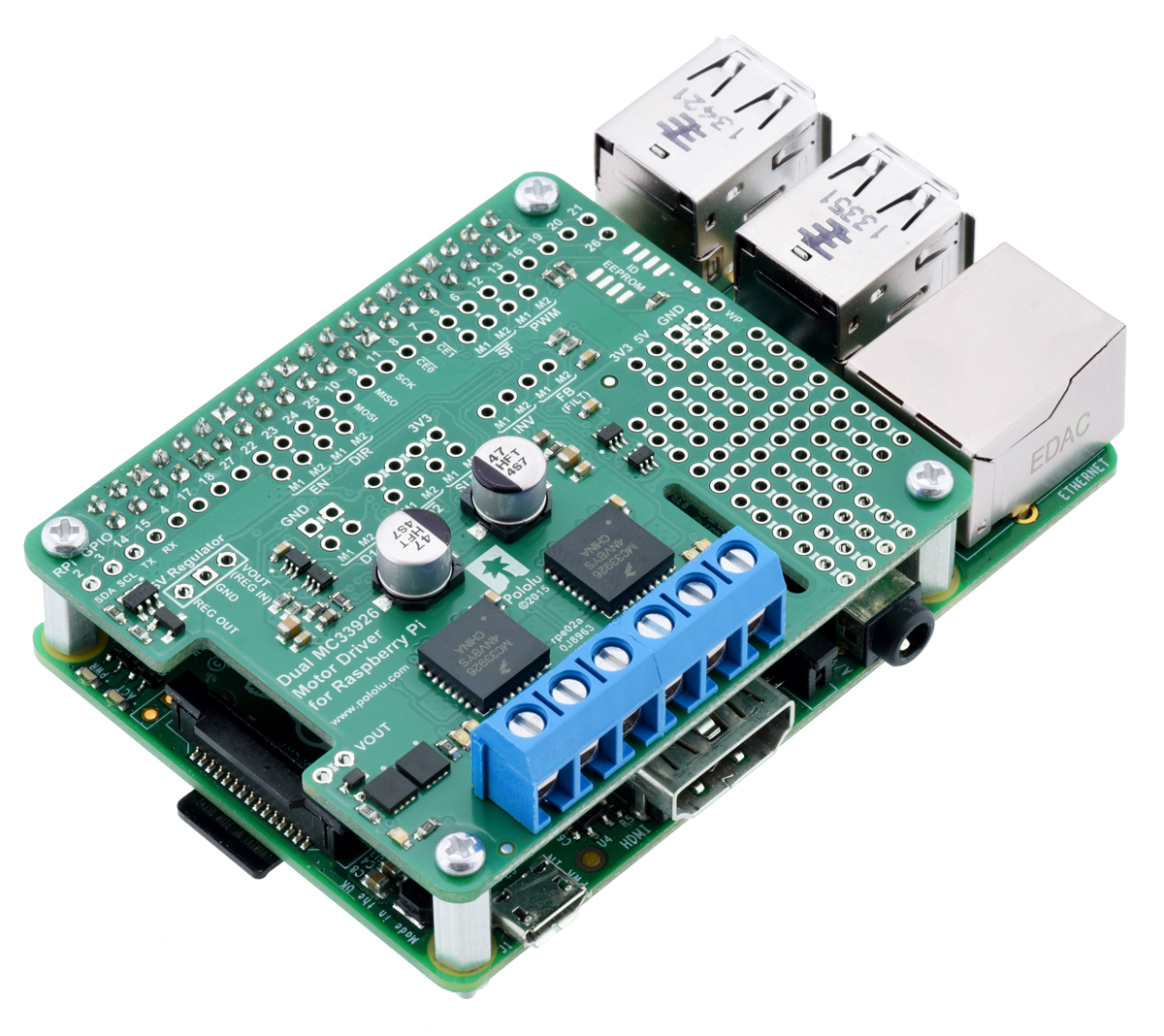
New Product: Dual TB9051FTG Motor Driver for Raspberry Pi

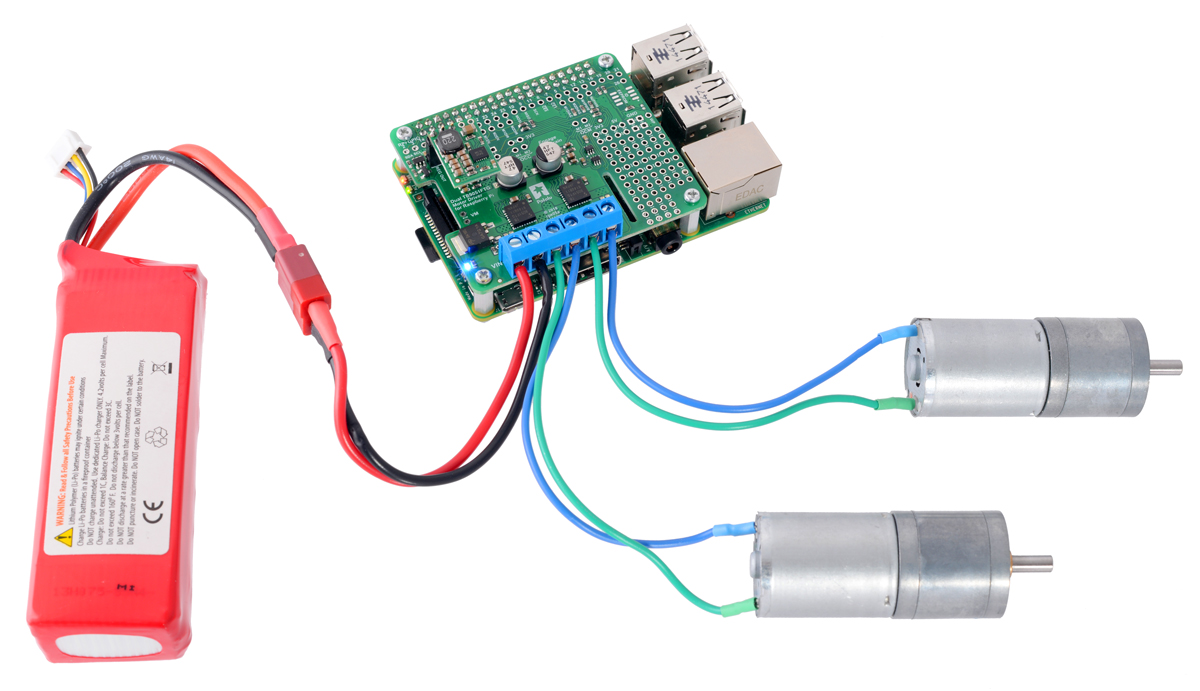
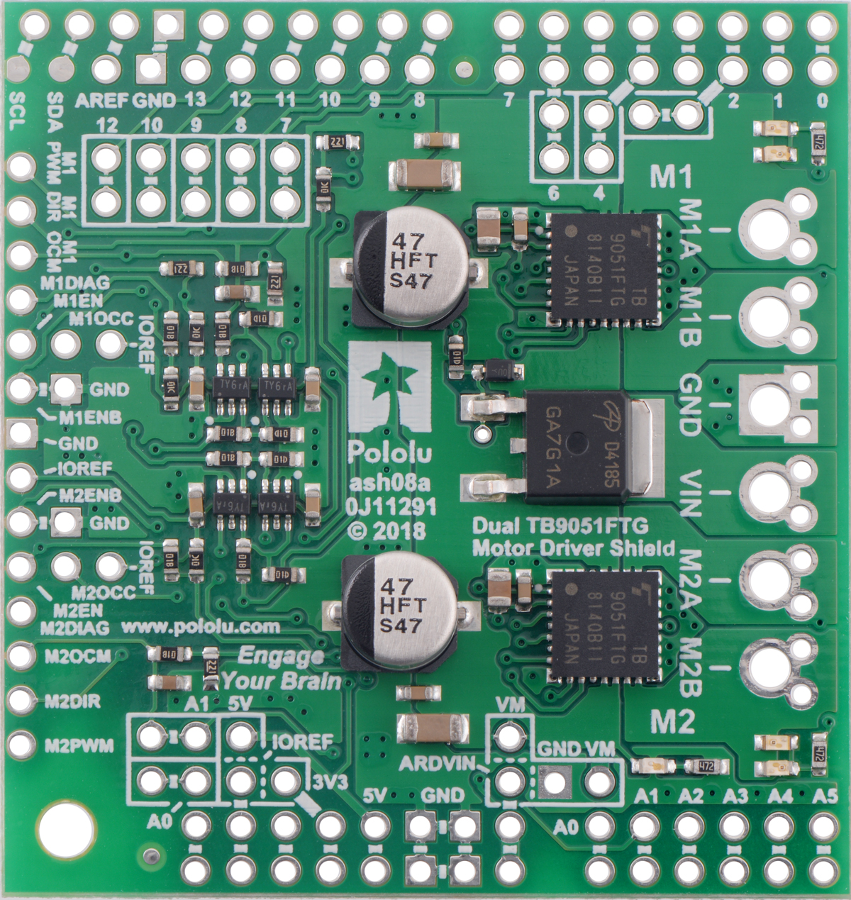
I am excited to share the second Pololu product for which I routed the PCB, the Dual TB9051FTG Motor Driver for Raspberry Pi. This board complements the TB9051FTG Single Brushed DC Motor Driver Carrier and the recently announced Dual TB9051FTG Motor Driver Shield for Arduino by making it easy to control two motors with a Raspberry Pi (Model B+ or newer).
The TB9051FTG can deliver a few amps across a wide operating voltage (4.5 to 28 V), which makes this expansion board ideal for controlling two small or medium size motors in your Raspberry Pi project. You can optionally connect a voltage regulator, like a D24V10F5 or D24V22F5 step down regulator, to power the Raspberry Pi with your motor power supply. The board also provides a prototyping area to help you construct clean custom circuits without the need for additional prototyping PCBs beyond the footprint of your Raspberry Pi.
 |
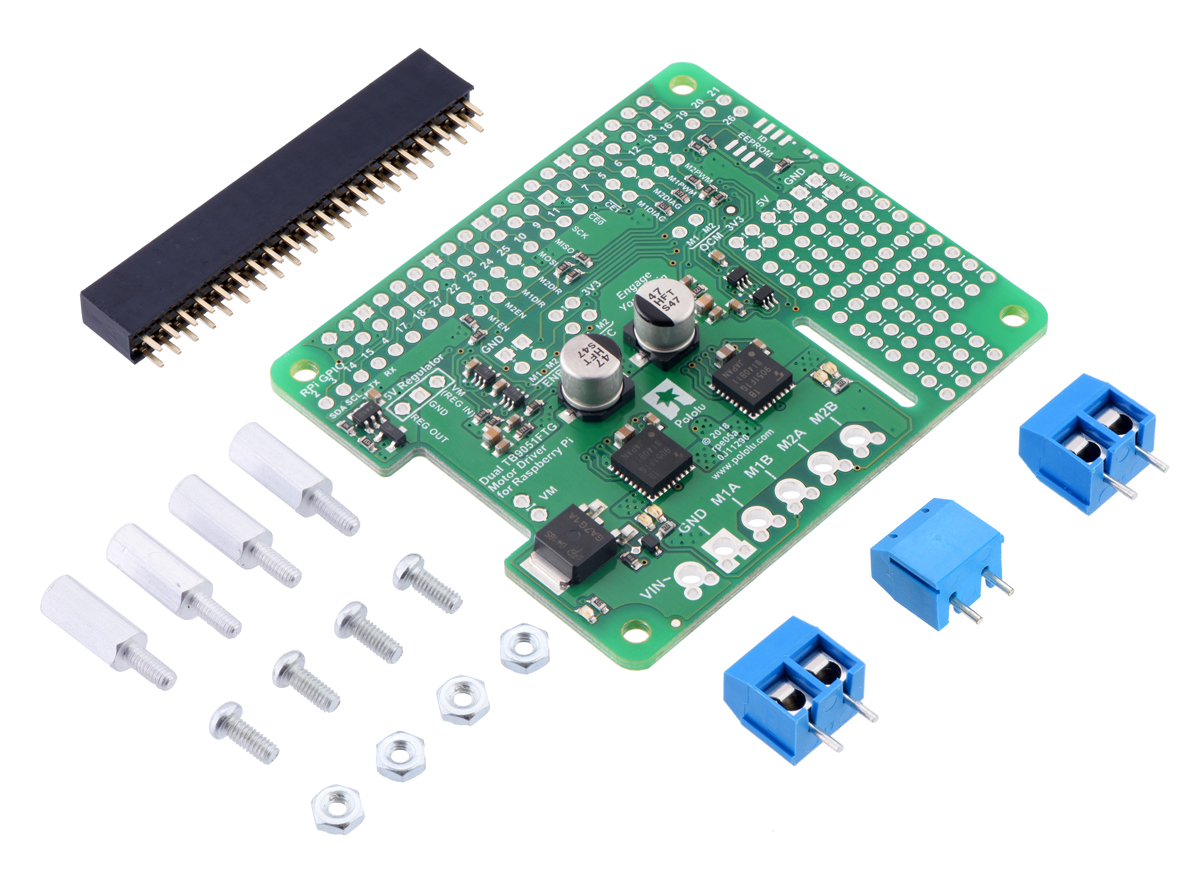
The Dual TB9051FTG Motor Driver for Raspberry Pi is available in two versions:
- a partial kit, with connectors included but not soldered in
- fully assembled, with the female header and terminal blocks soldered to the board
The board adheres to the Raspberry Pi HAT (Hardware Attached on Top) mechanical specification, although it does not conform to the full HAT specifications due to the lack of an ID EEPROM. (A footprint for adding your own EEPROM is available for applications where one would be useful.)
|
|

With the addition of this product, we now have eight Raspberry Pi motor driver expansion boards for you to choose from. To control more powerful motors, we offer various high-power motor drivers for Raspberry Pi. If you don’t need all the power provided by the TB9051FTG, consider our small and inexpensive DRV8835 Dual Motor Driver for Raspberry Pi or the dual MAX14870 motor driver expansion board (the first board I routed).
|
|

We have an introductory discount to go with this new product announcement. The first 100 customers to use coupon code RPITB9051INTRO can get up to two units for just $10.95 each. Note that this introductory offer applies only to the units without connectors soldered in. The introductory coupons for the single TB9051FTG carrier, the dual TB9051FTG Arduino shield, and some other products introduced this year are still available; you can see all the coupons available on our specials page.
Related products


New Product: Dual TB9051FTG Motor Driver Shield for Arduino
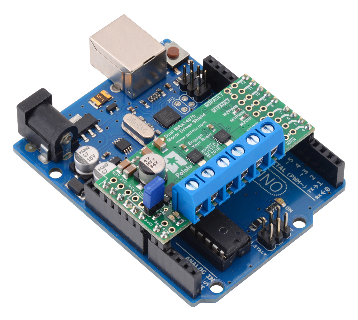
I am happy to announce the Dual TB9051FTG Motor Driver Shield for Arduino. It gives you two of our favorite integrated motor driver (you can read more about why I like it in my TB9051FTG carrier blog post) in the convenient Arduino shield form factor. You can also think of it as a lower-cost, slightly higher-performance version of our popular Dual MC33926 Motor Driver Shield for Arduino.
With a 4.5 V to 28 V operating range and the ability to deliver up to a few amps per motor, the TB9051FTG is great for a huge range of small hobby and toy motors that you might have available in your parts box or classroom.
|
|
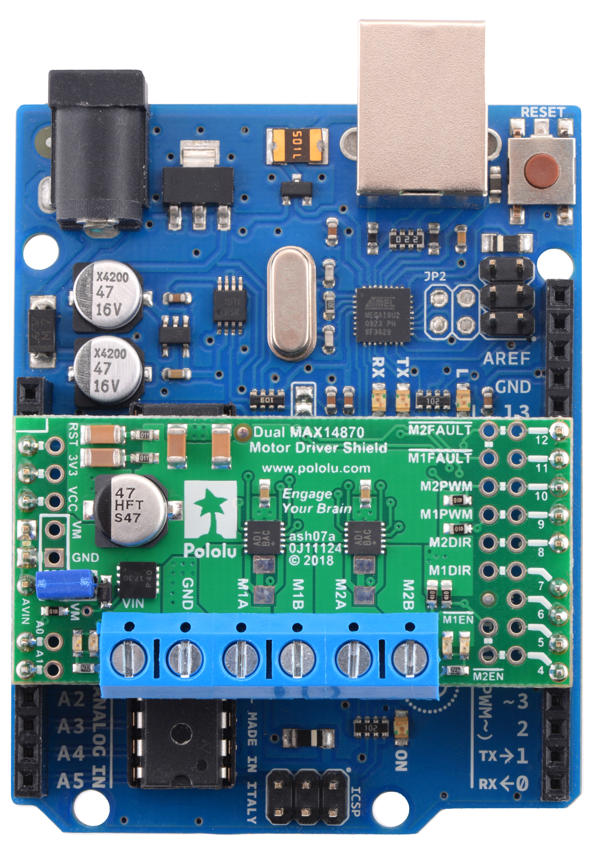
For those who don’t need all the power that the TB9051FTG can support, we also have the smaller (and lower cost) Dual MAX14870 Motor Driver Shield for Arduino.
|
|
As usual, we have an introductory discount to go with this new product announcement. Be among the first 100 customers to use coupon code TB9051SHIELD (click to add the coupon code to your cart) and get up to three units for just $9.97 each. The introductory coupon for the single TB9051FTG carrier is still available, along with some discounts for other products we have introduced this year; you can see all the coupons that are not used up yet on our specials page.
Related products

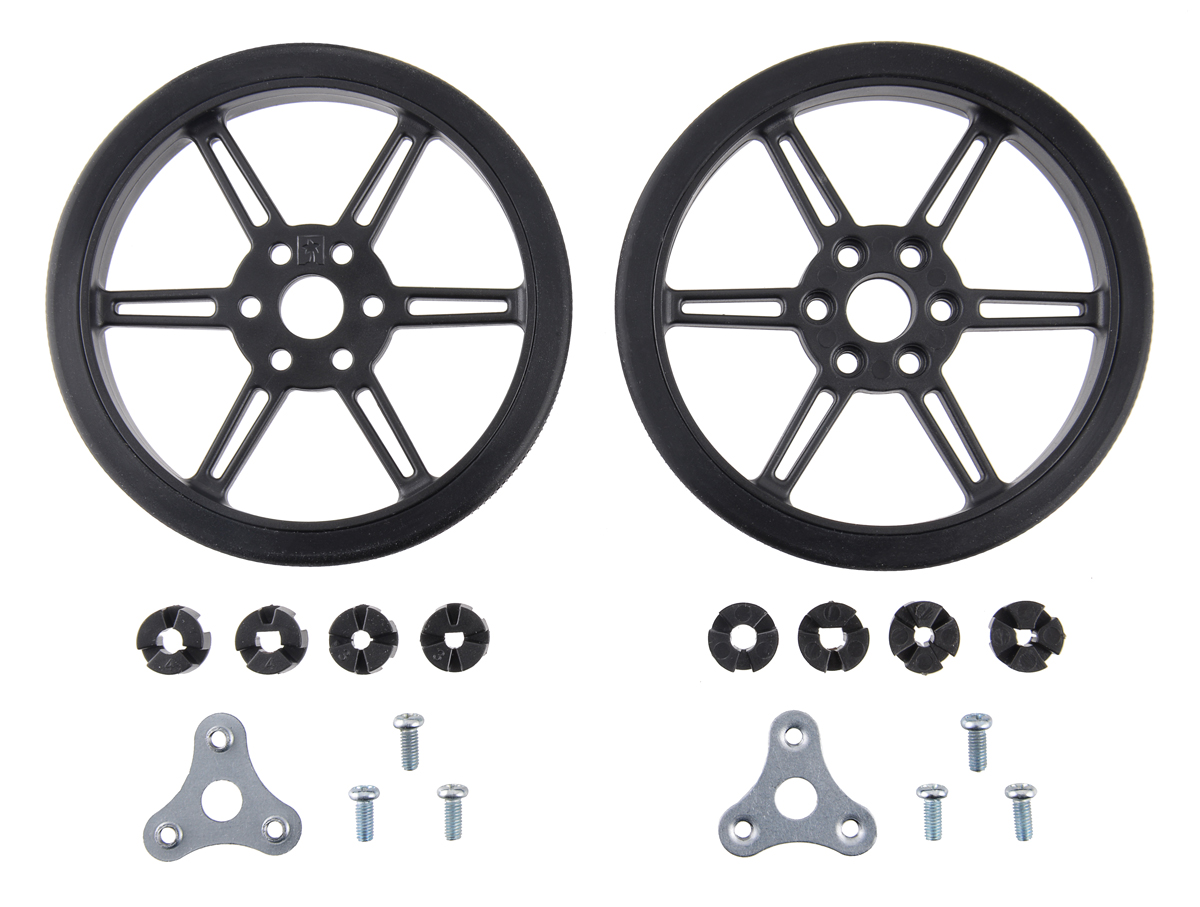
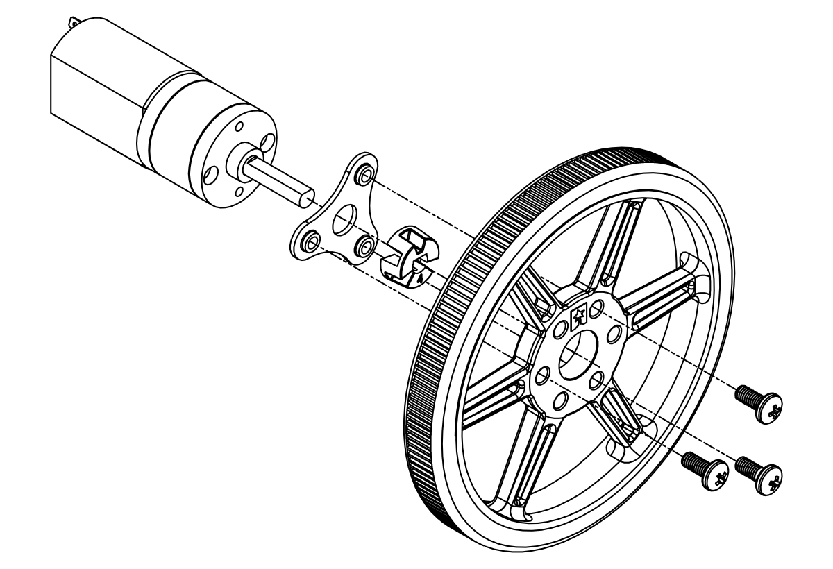
New product: 80×10mm wheels with multi-hub inserts for 3mm and 4mm shafts
 |
I have some exciting new wheels to tell you about (available as an 80×10mm black pair and an 80×10mm white pair). With a few small exceptions, all of the wheels we have made so far were for press fits (more properly called interference fit) onto 3mm D shafts such as those on our micro metal gearmotors. The press fit is simple and convenient for smaller motors and wheels, but there is an inherent trade-off between how hard you have to push to get the wheel on the shaft and how well the wheel stays on the shaft. As we contemplated designing some new wheels for our growing lines of 20D gearmotors and 25D gearmotors with 4mm output shafts (and higher power), I wanted something better. Our wheels already worked with our machined hubs with set screws, like this:
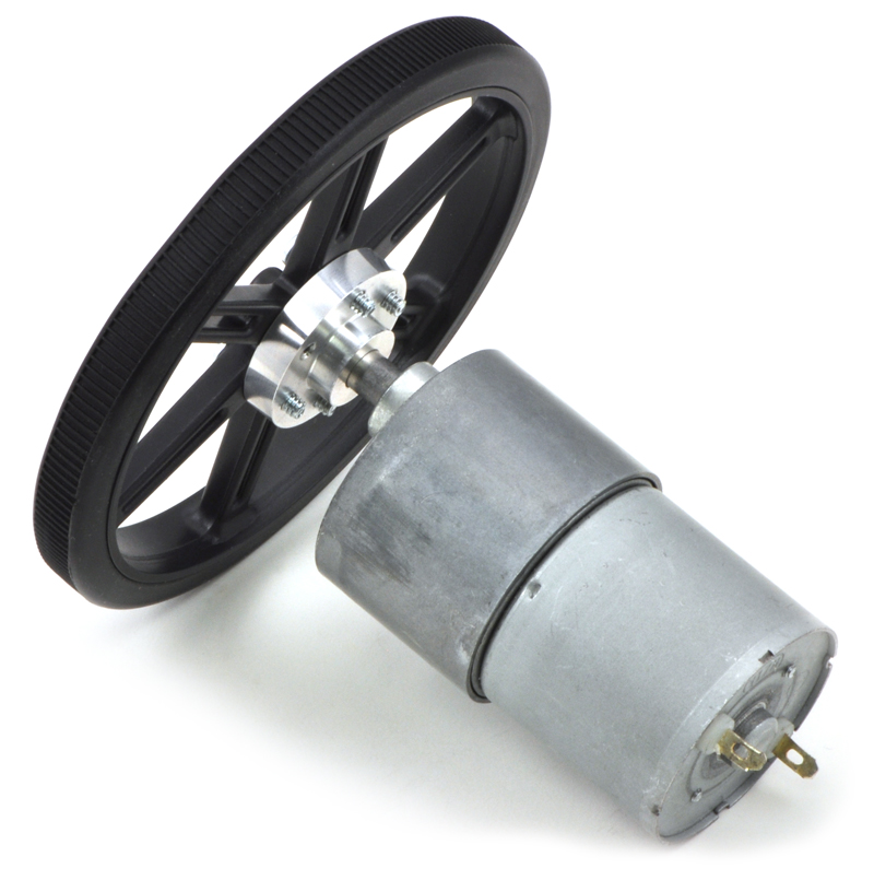 |
But the machined hubs are expensive, more expensive than the rest of the wheel. There’s also the much more minor issue of the machined hub option only allowing for the wheel to be placed at the very end of the shaft unless you drilled out the plastic wheel to have a hole larger than the shaft. I wanted to have an all-plastic, injection moldable solution that involved multiple parts that would somehow clamp the wheel onto an axle, kind of like a chuck on a drill.
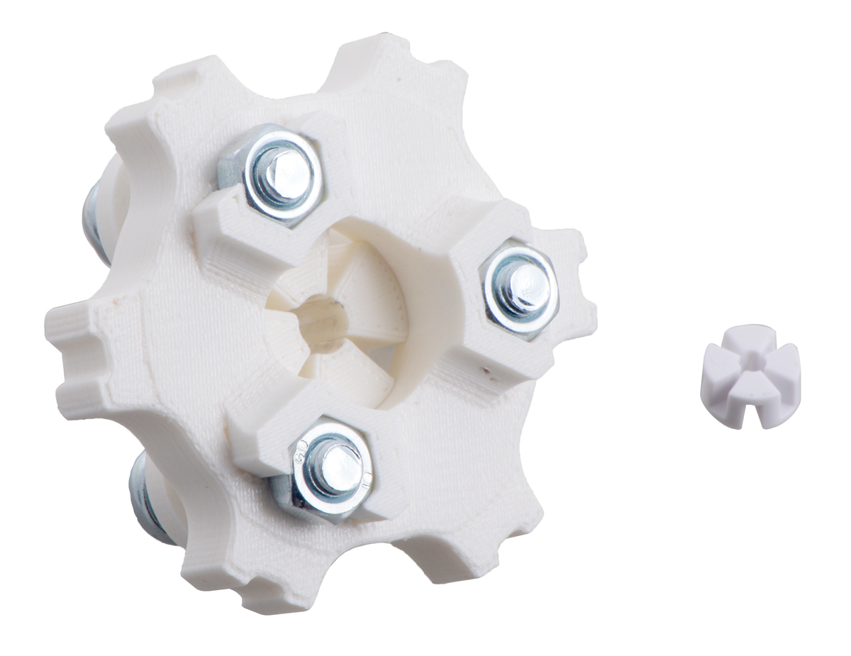
My initial idea was to have just two parts: the outer wheel and an inner, interchangeable collet that would get wedged between the wheel and axle. But our mechanical engineers were not able to come up with a single part that could both compress onto the shaft and attach rigidly to the outer wheel. Because the parts are so small, the resolution of our 3D printer limited the effectiveness of prototypes, so we worked with scaled-up models. This picture shows one earlier model next to the final production parts for scale:
 |
The other side of that model shows what we were thinking about for holding nuts in place on the back side of the wheel:
 |
At that point, we were at a three-component design, plus the three screws and nuts, which was turning out to be difficult to assemble onto a shaft, even if it worked. The screw heads needed to be accessible from the outside of the wheel so they could be tightened, and that left the nuts near the motor where they were difficult to access, and trying to make the wheel hold the nuts required the wheel to be toward the motor and the collet piece on the outside, which was less aesthetically appealing.
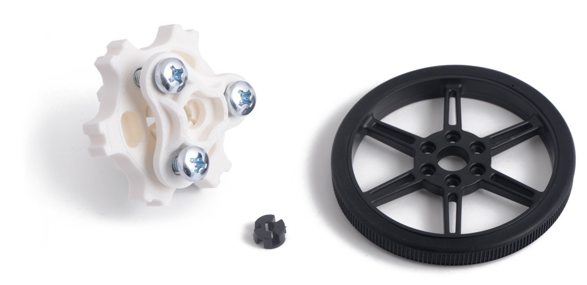
So, in the end, we gave up on my all-plastic goal and designed a single stamped plate with threaded holes that clamps the wheel onto the collet insert. It definitely makes the assembly much easier, as you can see from this expanded view:
 |
Having a design that seems like it might work on a 3D printed mock-up is still quite different from getting it working on the final, injection-molded parts. The clamping action of the collet inserts might have given us a little more margin for error than our usual press-fit wheels, but on those, a wrong fit is relatively straightforward to adjust: start with the fit a little on the loose side, and if it’s too loose, make the pin (and hole) smaller until it’s tight enough. With the new wheels, there were many more things that could go wrong, including alignment (wobbling). There was also the unknown of how much torque the hubs would take.
In the end, I think we arrived at a nice performance point. The wheels cannot take as much torque as if they were screwed on to the machined hub with set screw, but they can do much more than just the press fit hubs while putting less strain on the motor output shafts during installation. It’s possible to assemble the wheels with a little wobble, but if it’s a concern in your application, you can fiddle with how you tighten the three screws to get it as lined up as you like.
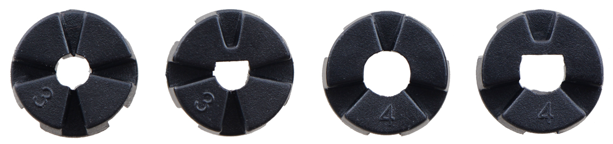
We started with our 80×10mm wheels, and made inserts that work with 3mm and 4mm shafts, both round and D-shaped:
 |
Since the concept seems to be working, we will be working on different wheel sizes and inserts for larger shafts later this year.
As with all our new product introductions this year, we are having an introductory special. Be among the first 100 customers to use coupon code MULTIHUBINTRO (click to add the coupon code to your cart) and get 33% off on up to three sets.

Related products


New product: Stability Conversion Kit for Balboa (and some memories of my first robot)
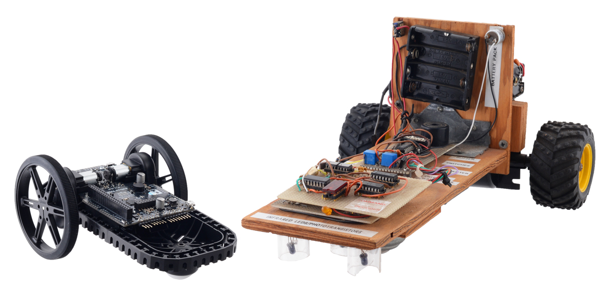 |
I don’t blame you if you have no idea why the new Stability Conversion Kit for Balboa is so exciting. With a name like that, you probably couldn’t even guess what it is, let alone why it’s exciting. But let me keep you guessing while I share a little about the first robot I built, which is kind of a hint. It’s pure coincidence that I happened to get reunited with it just as we were preparing to release this new product I’m announcing here.
I know for sure that I built my first robot in eighth grade, for the science and engineering fair for which everyone in my school had to do a project, which means I must have started working on it in 1992 when I was twelve years old. The better projects in my school went on to the local, island-wide science fair in Hilo, and the better projects there went on to the state fair in Honolulu. (I was initially not among those chosen to go on from the Big Island, I think because of some judging process mistake, but my science teacher and probably others lobbied to get me there.) There was time between the different stages, so I kept working on it through the spring of 1993, which would now make it over 25 years old. I probably added the labels in later stages in response to some advice to better present what I made.
 |
Jan’s first robot, “Robot Line Tracker,” built 1992-1993. |
|---|
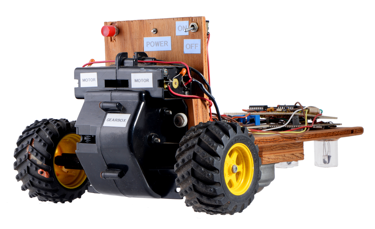 |
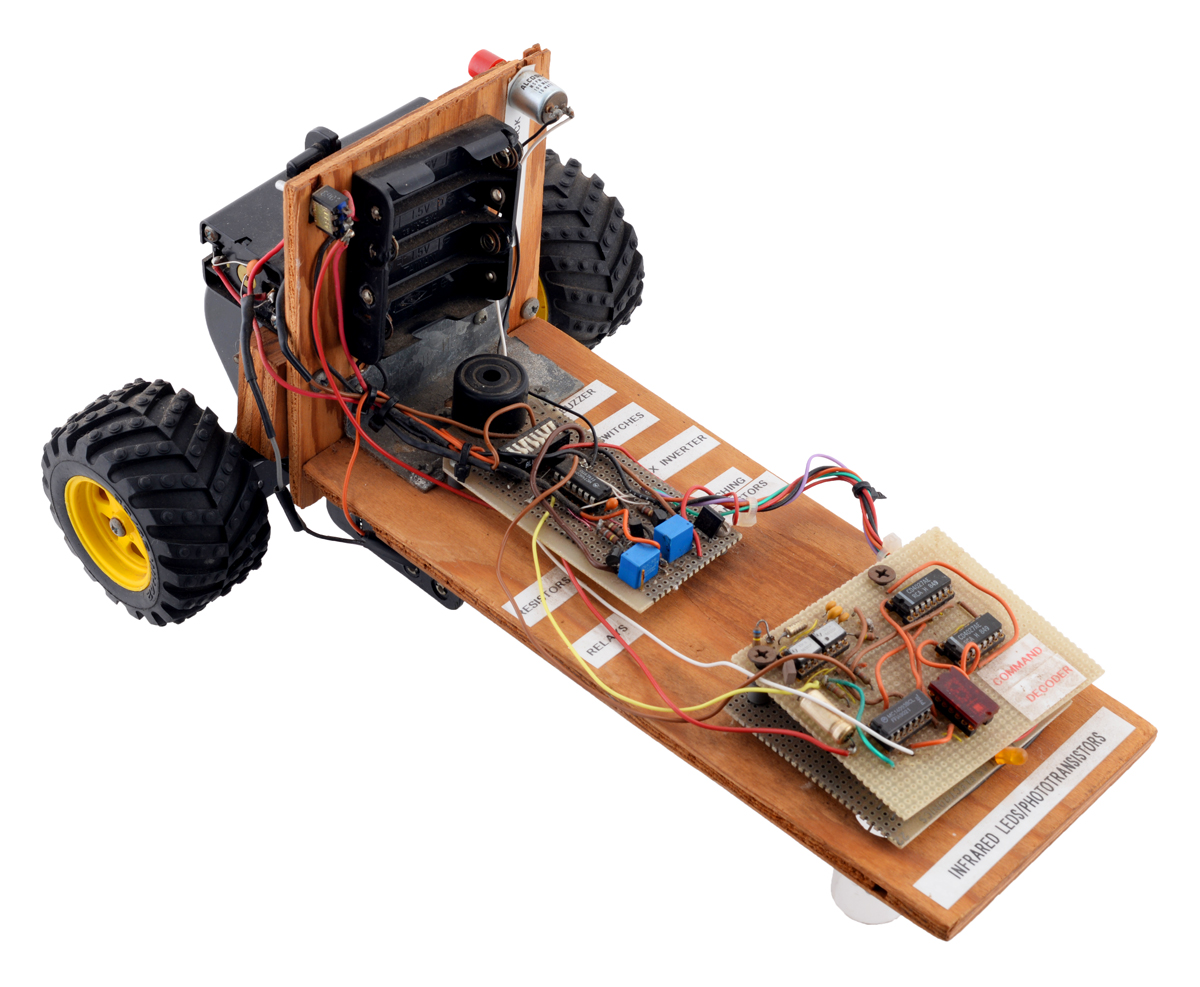
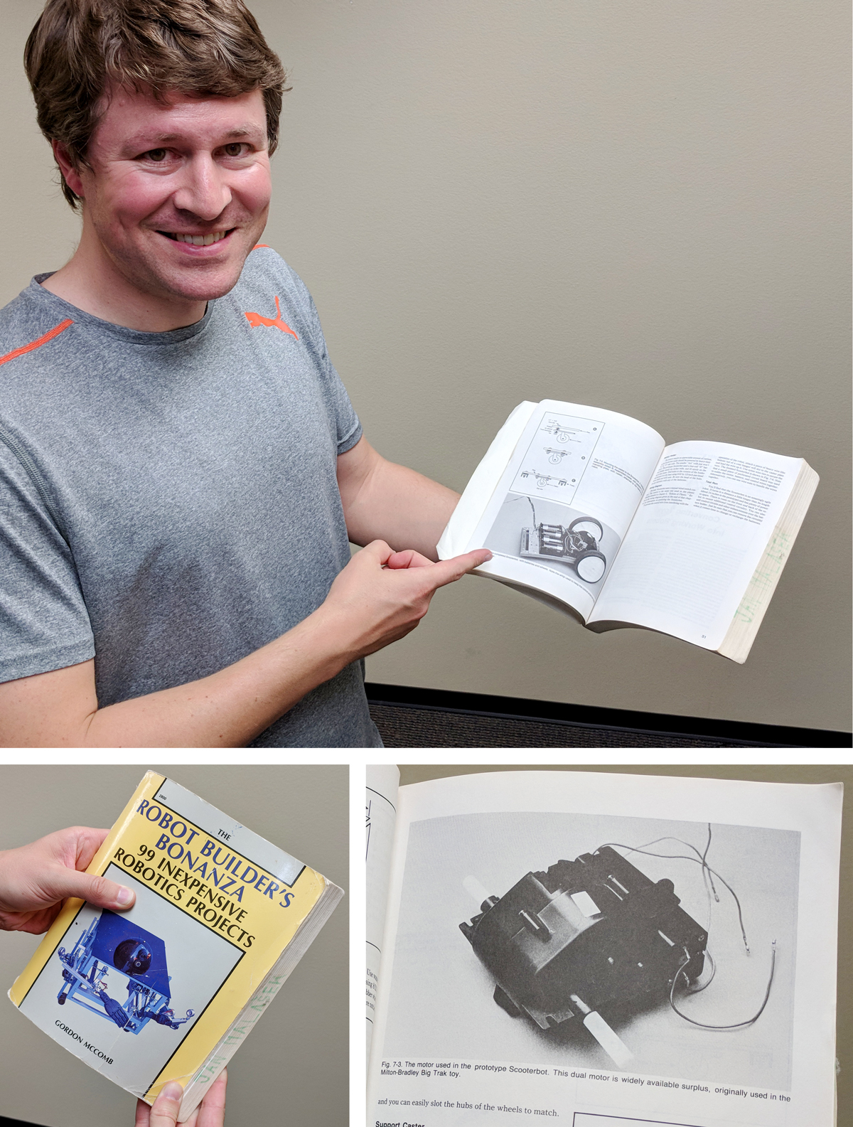
When Paul saw the robot for the first time in my office this morning, he immediately recognized a piece of it: “That looks like the gearbox from my first robot!” I was a bit skeptical, but he immediately backed it up by pulling out Gordon McComb’s Robot Builder’s Bonanza and showing me the project he had followed from the book. (In another amusing twist, it turns out that the copy of the book Paul had in his office is my old book, though I hadn’t gotten it until high school, and I didn’t realize until today that the gearbox in the book was the same one I had used.)
 |
I’m pretty sure I got the gearbox from Edmund Scientific, because their printed catalogs and Radio Shack (nearest one in Kona, 40 miles away) were initially my only sources for anything electronics-related. The wheels were from some broken radio control toy. The ball caster was long a point of frustration. In earlier versions of the robot, I had tried more common swivel casters and then a ball caster I made from a ping pong ball in a toilet paper tube, but neither was very reliable. I was very happy to eventually find the metal ball caster that I used in the final version, which you can see here along with the three IR LED and phototransistor pairs used for detecting a two-inch white line on a black background:
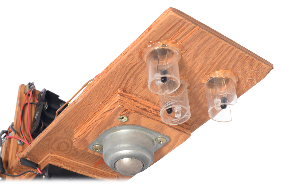 |
That heavy, noisy caster was not ideal, but at least it didn’t jam at a bad angle like the swivel caster or collapse like my ping pong ball and cardboard creations. I am mentioning all these details because it was so much work just to put a basic chassis together, without even getting to the electronics part. The electronics are not something I want to cover in this blog post, but I should mention that I was very fortunate to find a mentor at the Canada-France-Hawaii Telescope headquarters right across the road from my school. CFHT had a nice electronics lab stocked with all kinds of components they just gave me and tools they let me use, and I got lots of help from John Horne when I was in 8th grade and then from many others there while I was in high school.
So, to bring this back to Pololu’s new product: the Stability Conversion Kit for Balboa is primarily a ball caster attachment for the Balboa chassis:
 |
That might sound pretty basic, but using it fundamentally transforms the Balboa into a very different kind of robot. As a reminder, Balboa is a two-wheeled, balancing robot:
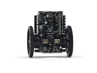 |
You can read more about the balancing robot in my blog post introducing the Balboa robot. It’s a very capable platform that we spent many years developing, but making a balancing robot is not easy, and it’s probably not the best type of robot to build as your first robot. We did not even release the chassis as a separate product independent of electronics because it would be difficult to do much with it. The new stability conversion kit completely changes that. With the ball caster, the chassis can be used as a much more beginner-friendly differential-drive mobile base with three points of contact with the ground:
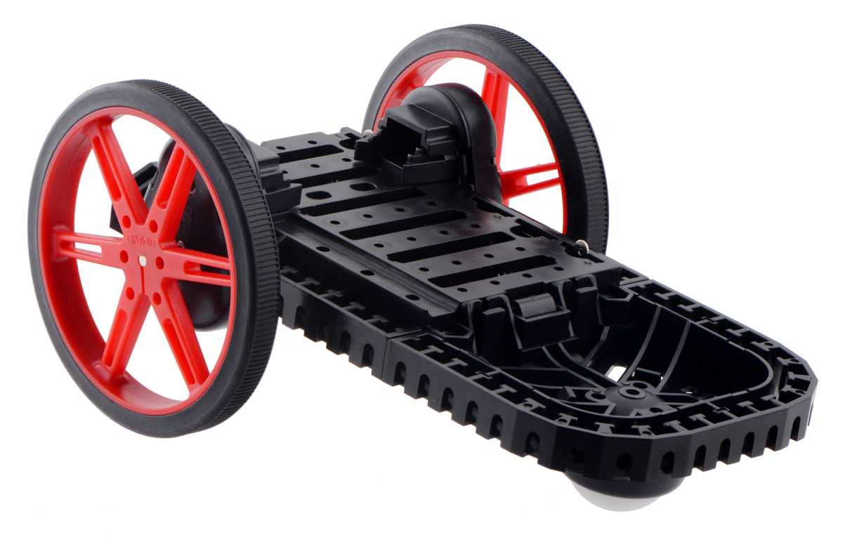 |
We offer the ball caster attachment by itself, for those who want to use it with a complete Balboa 32U4 robot kit to immediately get up and running without developing their own electronics. We also now offer the Balboa Chassis with Stability Conversion Kit, which includes all the mechanical components for the chassis other than wheels and motors:
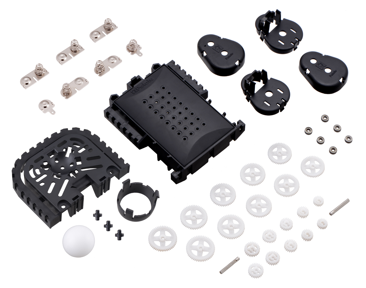 |
Balboa Chassis with Stability Conversion Kit (No Motors, Wheels, or Electronics). |
|---|
As with the original Balboa 32U4 kit that includes electronics, we deliberately do not include motors and wheels so that you can pick your own to customize the look and performance of your robot. This diagram shows the possible chassis angles with four different wheel sizes ranging from 60 mm through 90 mm:
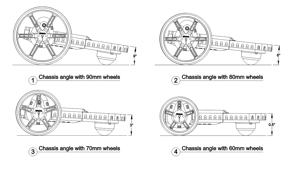 |
Variety of chassis angles available when using different wheels on the Balboa Chassis with Stability Conversion. |
|---|
 |
Micro Metal Gearmotor HPCB with extended motor shaft. |
|---|
For motors, we recommend our 30:1 HPCB, 50:1 HPCB, or 75:1 HPCB micro metal gearmotors with extended back shafts that can be used with encoders. Even if you do not plan on using encoders on your robot at first, it’s nice to have the option down the road.
And options are what our chassis kits are all about, whether you select our Zumo tracked chassis, Romi round chassis, or now the new Balboa chassis. One of my guiding principles in developing our robot platforms is that I want to help you, our customers, build your robot, not just the particular one we designed.
I realize there are many kids interested in robotics who are not as fortunate as I was to have Canada-France-Hawaii Telescope headquarters across the street from my middle school, and that for many of them (and their parents and teachers), all of the options we offer can be overwhelming. Over the next several years, we will be working on sensors and other modules specifically for the Balboa, along with combination bundles and tutorials that will make Balboa a platform that students can begin with as a basic first robot in middle school and keep expanding through higher levels of their education.
I’ll end this product introduction as I have all my product announcements this year, with an introductory special to encourage you to try the Balboa chassis out for yourself. Be among the first 100 customers to use coupon code BALBOACHASSIS (click to add the coupon code to your cart) and get 15% off on Balboa-related products (limit 4 per product).

Related products


New Products: TB67S249FTG and TB67S279FTG Stepper Motor Driver Carriers
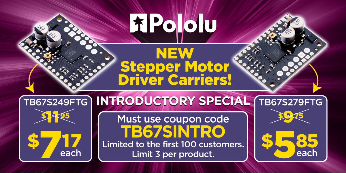
I am happy to announce the release of two new stepper motor driver products, carriers for Toshiba’s TB67S249FTG and TB67S279FTG. The only difference between the two is the maximum current supported, and with operation up to 47 V, the TB67S249FTG is our highest-power stepper motor driver. Both chips offer several innovative features, including Toshiba’s Active Gain Control (AGC):
Ben and I met with some Toshiba reps at the CES show earlier this year and got to see the demo setup shown starting from around 1:45 in that video, and it looks like it could be great for many applications where the drivers and motors are inefficiently running at maximum current all the time.
The folks at Toshiba were also excited about their Advanced Dynamic Mixed Decay (ADMD) feature:
The last special feature that I’ll point out is the internal current sensing, which Toshiba calls Advanced Current Detection System (ACDS). This is not very relevant when comparing our assembled breakout boards, but if you are considering using the driver chips directly in your own design, not having to add two big current sense resistors is a big plus.
 |
Because these stepper motor driver ICs have so many features, we made breakout boards larger than our usual small stepper driver carriers (popular on RAMPS and similar projects) so that we could fit all the necessary control pins. We are looking into the feasibility of fitting this chip into that smaller 0.6″ × 0.8″ form factor and what mix of features we would make accessible on it.
As with all of our new product announcements, we are offering an introductory discount to make it extra easy to try out these new drivers. Be among the first 100 customers to use coupon code TB67SINTRO (click to add the coupon code to your cart) and get 40% off on up to three units of each type.
Related products


New Product: TB9051FTG Motor Driver Carrier
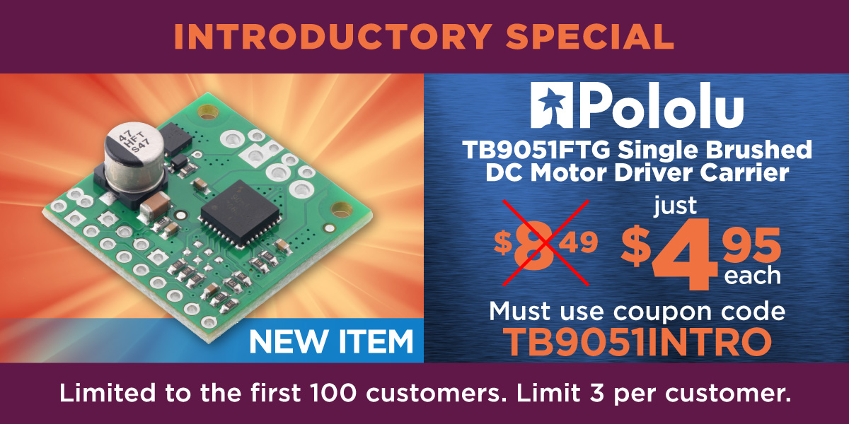
This is the second new motor driver product in less than a week, and I’m really excited about this one: the TB9051FTG from Toshiba. The TB67H420FTG I posted about the other day has this new part beat for higher voltages, but its one shortcoming for our purposes is that it doesn’t work at lower voltages. This new TB9051 doesn’t go up into those voltages where it starts getting dangerous, but it covers a great operating range of 4.5 V to 28 V, with transient operation to 40 V, which means you can use this driver with everything from 6 V lead-acid batteries and 2-cell LiPo packs all the way up to 24 V systems and 6-cell LiPo packs, maybe even 7-cell packs. The operating voltage range is similar to another recent favorite of mine, Maxim’s MAX14870, but this new Toshiba part delivers almost double the current.
 |
Pololu dual MC33926 motor driver (assembled) on a Raspberry Pi Model B+. |
|---|
With its excellent operating voltage range and great current ability for an integrated package, I expect the TB9051 to be an ideal all-around DC brushed motor driver for most indoor robots and other projects that do not involve moving frighteningly large objects at potentially catastrophic speeds. The chip seems positioned to compete performance-wise with my previous almost-favorite chip, the Motorola Freescale NXP MC33926. That chip would have been my favorite if it had been easier to work with Freescale, and things have only gotten worse since NXP acquired them and then got distracted by yet another merger, this time with Qualcomm, which seems to have been in limbo forever. Maybe their sales are actually doing great, and we just have a hard time with them because they are busy with bigger customers. In any case, a part with great performance is not so great overall if it’s difficult to get it, so you can expect us to be updating some of those products that use the NXP part to use the Toshiba part instead.
One pretty obvious feature the TB9051 has over the MC33926 is its smaller size, from 8 mm x 8 mm down to 6 mm x 6 mm, which is great for getting these onto smaller boards in smaller spaces, but it might also have some ramifications for how it tolerates pushing the limits of the specs. We liked how the MC33926 was able to endure lots of abuse from customers who were pushing it because it was our highest-voltage integrated driver. The TB9051 is, like the MC33926, an automotive-rated part, so it is intended to last a long time in harsh conditions. It’s interesting to see how thick the packages for these chips are, and I like their thickness (similar to how I like the proportions on 737 airplanes):
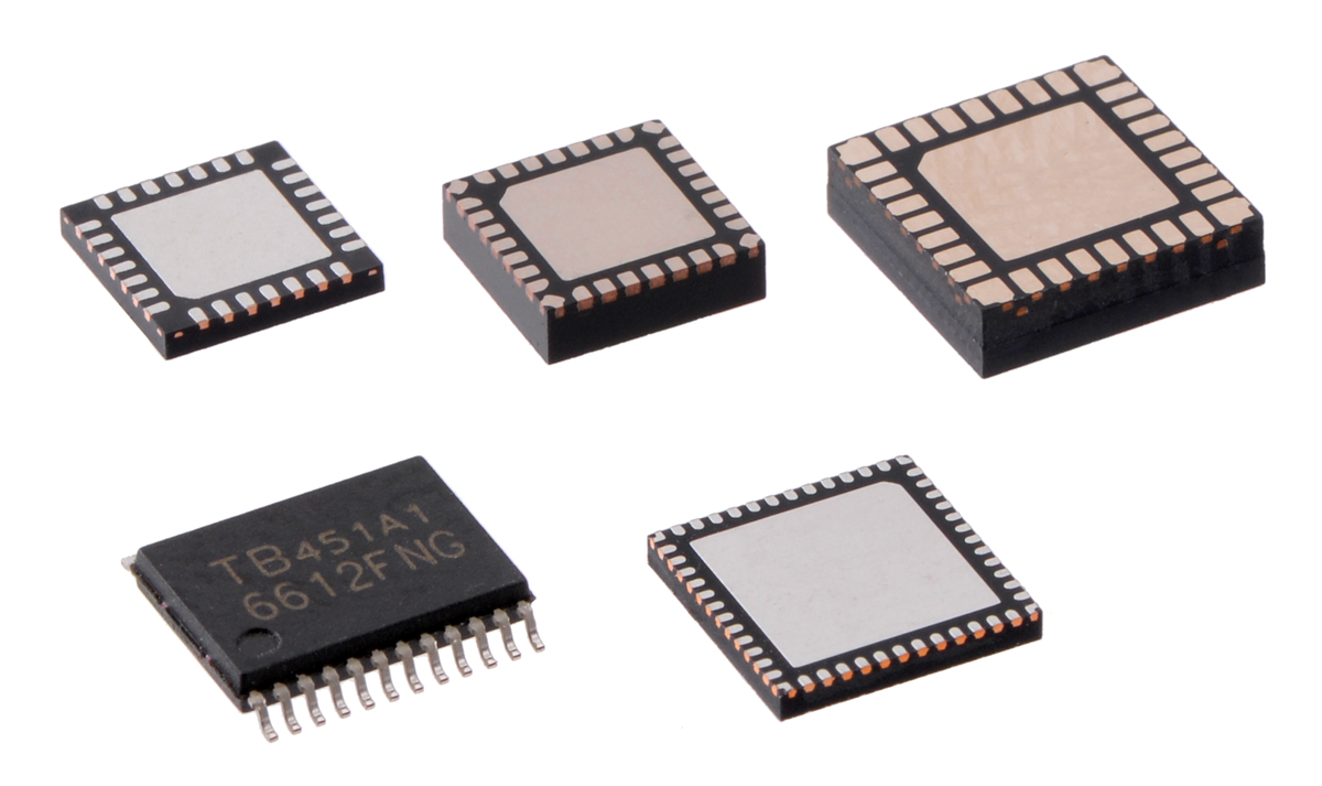 |
Clockwise from upper left: packages of a 28-pin microcontroller, TB9051FTG, MC33926, TB67H420FTG, and TB6612FNG. |
|---|
This video makes it seem like Toshiba is quite proud of their packaging accomplishment with the TB9051FTG:
Update: It looks like the above video might no longer be available on youtube, but it is still available on the Toshiba website.
Is the “competitor” in this video the MC33926? Sure seems like it to me. I know of no other part like that, and I keep looking.
Toshiba has not publicly posted a complete datasheet for the TB9051FTG yet, so the product page for our carrier only has a preliminary summary document. Our product page has more information about how to use the device, and we are working on getting a complete datasheet that we can post.
Since I expect this driver to hit a nice sweet spot for many of our customers’ general-purpose motor control needs, it’s a good candidate for using in some higher channel count products. We have not gone much beyond two motors (the TReX motor controllers have a third, unidirectional channel), and I would like to know what kind of interest there is in single boards that can control three or more motors. If you would like to see such products, please let me know.
As with all of our new product announcements, we are offering an introductory discount to make it extra easy to try out these new drivers. Be among the first 100 customers to use coupon code TB9051INTRO (click to add the coupon code to your cart) and get up to three units for just $4.95 each. We are still manufacturing our initial stock of these, and even if the quantity shown online goes to zero, you can backorder with the coupon price and chances are that we will be able to fill your order the same day.
Related products


Updated product: A-Star 32U4 Mini SV
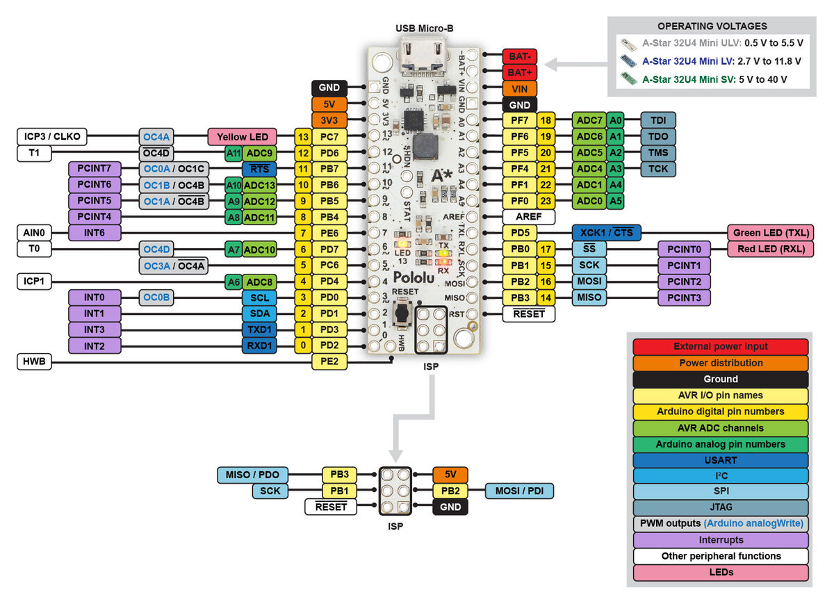 |
A-Star 32U4 Mini pinout diagram. |
|---|
I think of our new A-Star 32U4 Mini SV as more of an update than a genuinely new product. For those of you not already familiar with our A-Star 32U4 Minis, they are a series of ATmega32U4-based, USB-programmable controllers with integrated switching regulators that offer operating voltage ranges not available on typical Arduino-compatible products; the “SV” variant features a step-down converter that enables efficient operation with inputs as high as 40 V. The slight PCB update for this latest product was done primarily for manufacturing reasons (e.g. reset button footprint change, addition of a test point, and switching to an ENIG finish that has worked better for us for double-sided assembly), but I figured that while we were updating all our internal records for the new PCB, we might as well also upgrade the regulator.
There’s a difficulty to making small improvements to products when we have hundreds of distributors around the world since even if we clear out our inventory of older versions before shipping newer units, we cannot control the inventory at distributors’ warehouses. We’re all usually tolerant of products being a little better than advertised, but when we try out a product, and then buy another one, and it ends up being worse than the one we already had, it just doesn’t feel right. (That’s one reason we sometimes do not reveal exact components we use, to avoid over-specifying some aspect of a product that we feel is not that important and that we do not want to commit to.) Once the regulator was different (and better!) enough to merit changing the product specifications, we needed to change the product number, and hence we have a new product.
The regulator change is from the ISL85415 to the ISL85418, both made by Renesas (which acquired Intersil). The ISL85415 was the first of a great regulator family by Intersil, and they expanded the family with several pin-compatible versions with various current specifications. These new parts could also operate to 40 V instead of the 36 V of the original ISL85415, but even as various aspects of the datasheets got updated, the maximum voltage rating on the ISL85415 in particular did not.
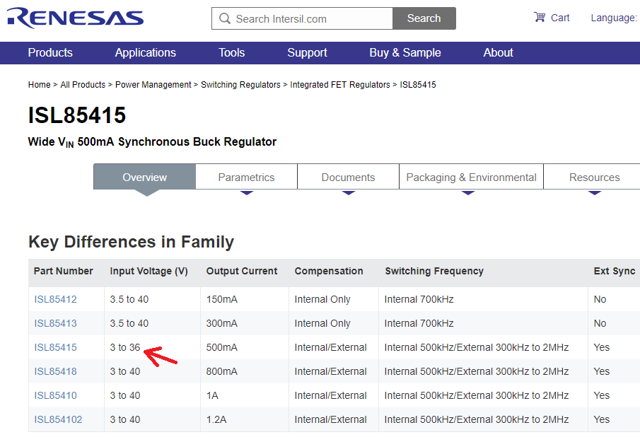 |
Renesas website screen capture showing ISL85415 is only part in its family with 36 V maximum input. |
|---|
I asked our Intersil contact about why only the ISL85415 wasn’t rated to 40 V. It sounded like it was getting made on the same process as the other parts, and that the higher voltage rating of the later parts in the family was more the result of better characterization (and thus confidence) in the process than in any modifications to the process. In other words, new ISL85415 parts can probably do 40 V just like the other parts, and the older ISL85415 parts probably the same; they just weren’t confident about calling them 40 V parts then. But who knows what the inside story is. Maybe they did tweak their recipes a bit, and once they had parts out in the world with the 36 V spec, they didn’t want to change it without changing the part number, just like we couldn’t just keep our old A-Star part number and also talk about the higher maximum input voltage.
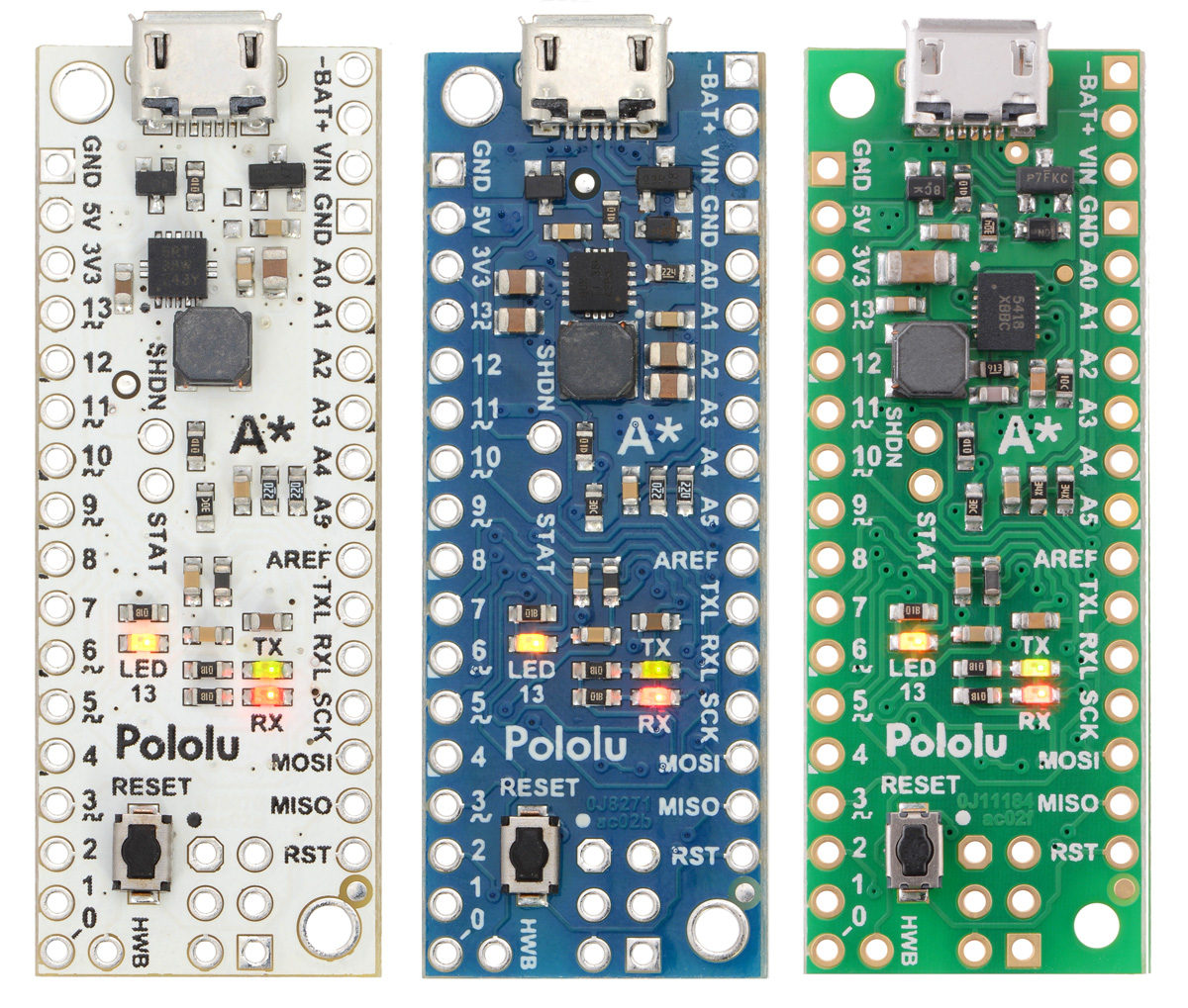 |
A-Star 32U4 Mini ULV, LV, and SV. |
|---|
In case you’re wondering why we didn’t just put the even better ISL85410 or ISL854102 with 1.0 A and 1.2 A outputs on the new board, it’s because the performance limit moved more to the inductor, and even if the better regulator chip takes up the same space, we would need a bigger inductor to take advantage of that. And the A-Star Minis are pretty packed designs, so there’s not much room for a bigger inductor.
So, to make a long story short, the main new feature of the updated A-Star 32U4 Mini SV is that it can now take up to 40 V input and give you up to 800 mA to work with. This chart shows you what the new regulator (in darker green) can do compared to the older one (lighter green) on the A-Star Mini. It looks like the old one already provided well over its 500 mA specification.
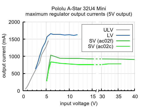 |
Typical maximum output current of the regulators on the A-Star 32U4 Mini boards. |
|---|
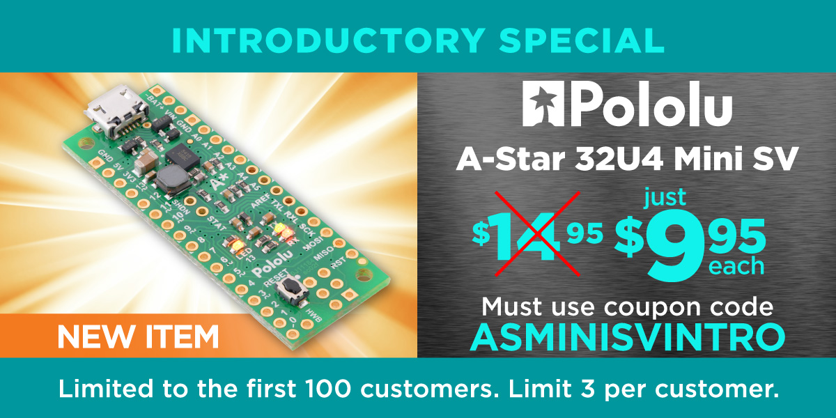
To make this new product a little more exciting, we reassessed our costs and cut some of our margins in keeping with our push this year to be more competitive in our manufacturing. We have reduced the unit price from $19.95 to $14.95. And as usual for our new product releases this year, we’re offering an extra introductory discount: use coupon code ASMINISVINTRO to get up to three units for just $9.95. (Click to add the coupon code to your cart.) Our promotion banner shows the usual limit for the first 100 coupon uses, but since we’re also having our Arduino Day sale, we’re removing that restriction for the duration of the sale. If we run out of stock during the sale, you can still backorder with the discount, and we should be able to catch up with production within a few days.
Related products


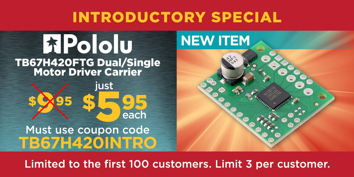
New product: TB67H420FTG Dual/Single Motor Driver Carrier
Hey! We have a new dual motor driver carrier for Toshiba’s exciting TB67H420FTG that offers quite the power jump from the TB6612FNG we popularized over a decade ago. This chip has a recommended operating range of 10-47 V and can deliver peaks of 4.5 A per channel. In our tests on this carrier, without additional heat sinking or airflow, the maximum continuous current is about 1.7 A per channel.
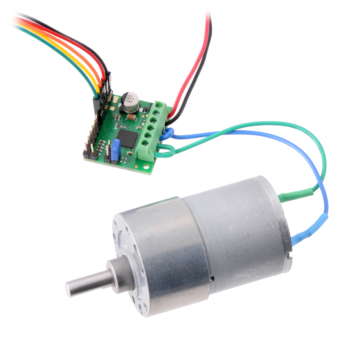 |
TB67H420FTG Dual/Single Motor Driver Carrier driving a motor in single-channel mode. |
|---|
One of the most common questions we get about our motor drivers is whether the outputs can be paralleled to drive a single bigger motor. The TB67H420FTG specifically has that feature built-in so that you can safely do that while only requiring control signal connections for one channel. This brings the available current for single-motor operation to 9 A peak and about 3.4 A continuous.
The TB67H420FTG has a maximum supply voltage of 50 V, making it one of the highest-voltage drivers we have available. Please note that we populated with 50 V capacitors on the supply line, so there is less margin there than on our usual products if you want to push the upper voltage limits of this chip. As with most of our carriers, we also added reverse voltage protection. The MOSFET we use for that is a 40 V max MOSFET, so the maximum reverse voltage that it protects you from is that same 40 V. If you’re wondering why we didn’t use higher-voltage parts, it’s because the next standard voltages are much higher, 100 V in the case of the capacitors. Getting the same capacitance at that rating would require bulkier, more expensive capacitors for almost no benefit. I’m telling you here in case you are one of those people who like to put 55 V on a 50 V max part just to see what will happen.
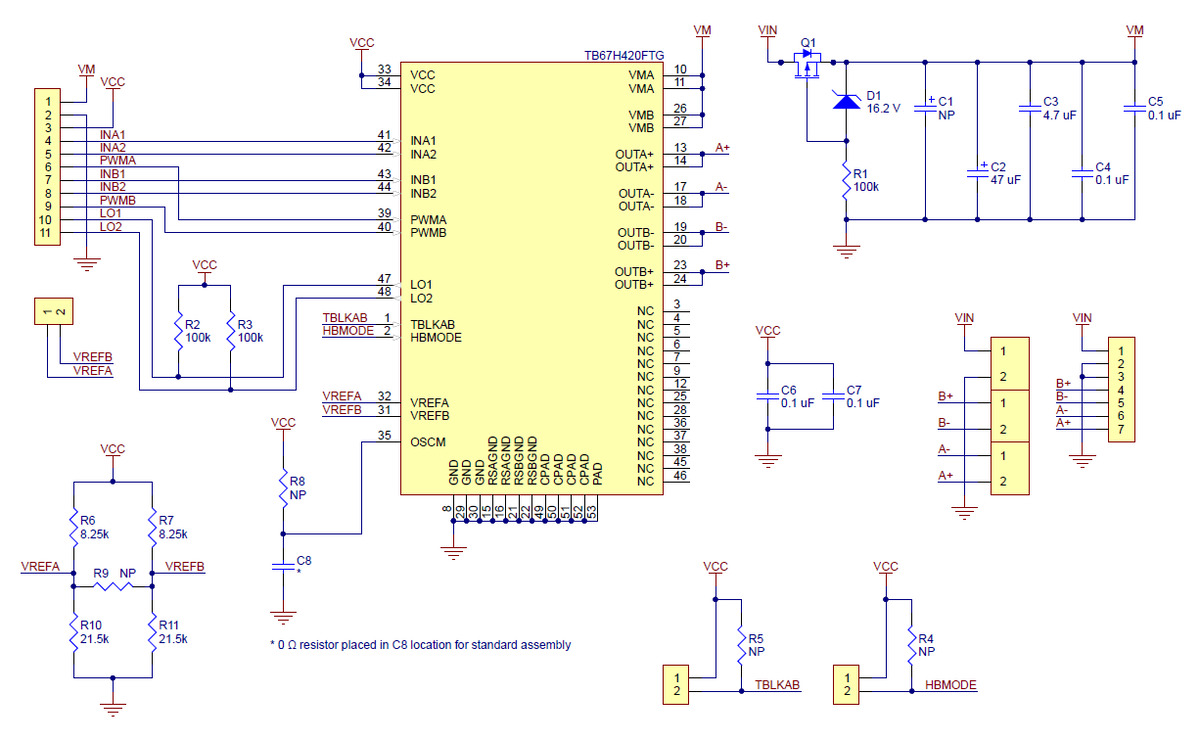 |
Schematic diagram of the TB67H420FTG Dual/Single Motor Driver Carrier. |
|---|
Be among the first 100 customers to use coupon code TB67H420INTRO (click to add the coupon code to your cart) and get up to three units at the introductory special price of $5.95 each. The first batches are just coming out of production, so even if the available stock goes to zero, you can still backorder with the coupon price and chances are that we will be able to fill your order the same day.
Related products

New product: VL53L1X Time-of-Flight Distance Sensor Carrier

The carrier board for the VL53L1X that many of us have been waiting for is finally here! The VL53L1X is ST’s newest time-of-flight (ToF) range finder for which we first saw announcements over a year ago, but they were not available to us for ordering until earlier this year. The part is pin-compatible with the earlier VL53L0X, so we were able to put them on the same PCB as we use for that carrier as soon as our first reel of new sensors came in.
Be among the first 100 customers to use coupon code VL53L1XINTRO (click to add the coupon code to your cart) and get up to five units at the introductory special price of $8.88 each. We have a few hundred made to begin with, and we are continuing to make more, so even if the available stock goes to zero, you can still backorder with the coupon price and chances are that we will be able to fill your order the same day.
Related products


New products: Jrk G2 USB Motor Controllers with Feedback

After many months or years of work (depending on how you look at it), I am happy to introduce our newest motor controllers, the Jrk G2 USB Motor Controllers with Feedback, which we are releasing today in four power variants:
 Jrk G2 18v19 |
 Jrk G2 24v13 |
 Jrk G2 18v27 |
 Jrk G2 24v21 |
|
|---|---|---|---|---|
| Recommended max operating voltage: |
24 V(1) | 34 V(2) | 24 V(1) | 34 V(2) |
| Max nominal battery voltage: |
18 V | 28 V | 18 V | 28 V |
| Max continuous current (no additional cooling): |
19 A | 13 A | 27 A | 21 A |
| Dimensions: | 1.4″ × 1.2″ | 1.7″ × 1.2″ | ||
1 30 V absolute max.
2 40 V absolute max.
 |
The main purpose of the Jrk G2 family is to enable feedback-based control of DC brushed motors, simplifying closed-loop control of things like the position of an actuator. An example that is probably familiar to most of us is the common hobby servo that has an output shaft that can rotate to various positions as commanded over a simple interface. The Jrk motor controllers can be used for giant versions of those servos, and they can also be used in many other systems as long as you can somehow get feedback in the form of an analog voltage or a frequency. Analog voltage feedback is often easy to get from potentiometers that can serve as angle or position sensors.
The frequency feedback feature is handy for maintaining a speed of a motor independent of your supply voltage and motor load. You might use that kind of feature to run a treadmill at some set speed independent of the weight of the lab rats on it or to stir some jar of goop at a constant rate as the goop gradually thickens. With mobile robot applications, it can be handy to have a motor controller that will make your wheel go at the speed you set independent of whether the robot is on a hard floor or a carpet. (The Jrks do not support quadrature encoders, but you can use one channel of a quadrature encoder as the tachometer for the Jrk. In some applications, keeping track of absolute position is not necessary, or the quadrature encoder can be monitored directly by a main controller that could still benefit from the closed-loop speed control being taken care of by the motor controller.)
To control a wide range of motors in a variety of applications, it’s important to be able to configure a lot of parameters, which makes the Jrk’s USB connection and free configuration utility software extremely important. Even if you ultimately want to use your Jrk in a radio control installation or command it over I²C from your favorite embedded controller, it’s very convenient to be able to set everything up from your computer.
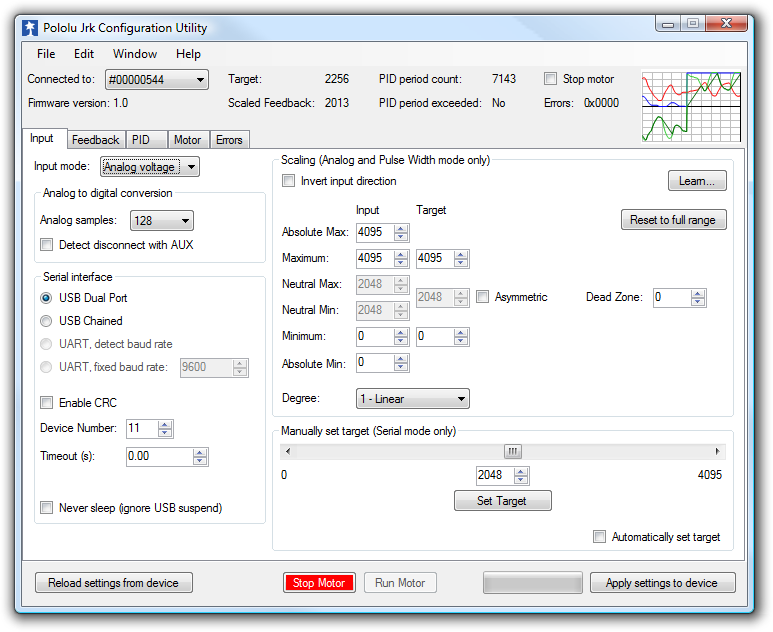 |
That screenshot is actually of the utility for the original Jrks, which we released almost 9 years ago (I announced those on the forum because we did not have this blog back then). You might notice on some older web pages that we referred to the original Jrks as our second-generation feedback controllers. The really original ancestor to today’s new motor controllers is this product we called simply Pololu 3A Motor Controller with Feedback, which we released at the beginning of 2005. Here are a picture and block diagram of that controller:
|
|
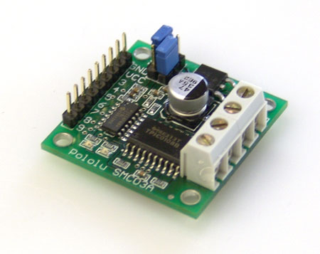
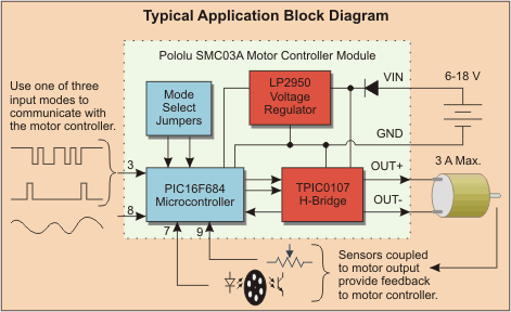
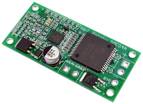 |
Candice and I were probably still running Pololu out of our house back when we started work on that controller, and it’s probably the last product of ours for which Candice wrote some of the firmware. That controller led to the development of a larger, customized controller (similar to our SMC04 High-Power Motor Controller with Feedback) and an even higher-power version that was used on control cables of large autonomous parachutes for the military.
Back to the new Jrk G2 family: these new controllers are in many ways a refinement of the original Jrks, which have been used all over the world in applications from animatronic displays to motion simulators and even full-sized airplanes. The most noticeable improvement on the four Jrk G2 controllers we are releasing today is the increased power available from their discrete MOSFET H-bridges. The G2 high-power motor driver design is part of the reason for the “G2” in the new Jrk family name, though we plan on releasing lower-power, smaller Jrk G2 products later this year. The new driver technology, along with going to double-sided PCB assembly and four-layer PCBs, allowed us to make much higher-power controllers that are smaller than the old Jrk 12v12, which used to be our highest-power version.
The Jrk G2 24v13 and 24v21 in particular open up new application opportunities because they can operate off of 24 V power rails, making them appropriate for huge linear actuators (note that we only carry 12 V versions right now, partly because we did not have controllers that we could recommend for 24 V use). It’s exciting that these tiny boards can control such huge actuators, and the size difference is so big it’s difficult to convey in a picture:
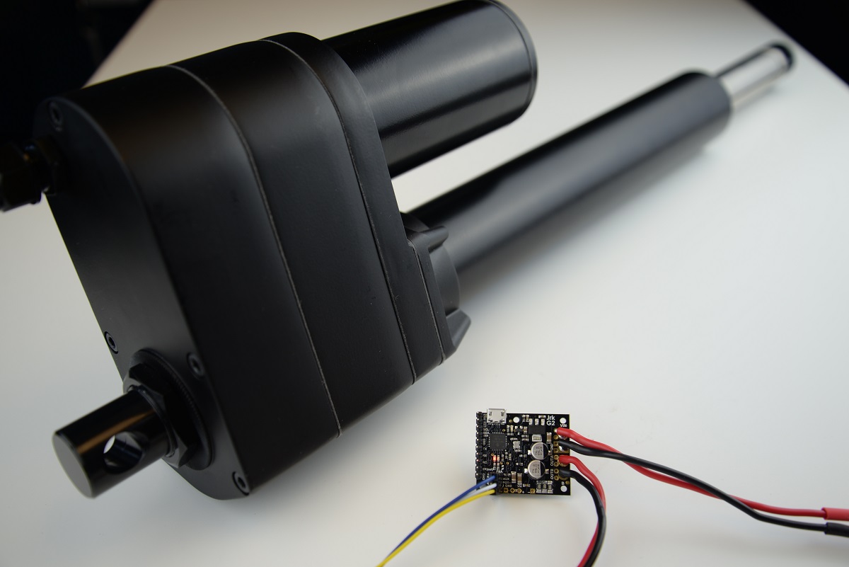 |
The size difference makes it difficult to get a Jrk G2 24v13 and an industrial-duty linear actuator in the same picture. |
|---|
Other features new to the G2 Jrks are an I²C interface option and an improved tachometer/frequency feedback mode that now offers pulse width measuring rather than only frequency counting to allow for better control of low-speed motors with lower-resolution encoders or tachometers. Here is a summary of the main features of the Jrk G2 motor controllers:
- Easy open-loop or closed-loop control of one brushed DC motor
- A variety of control interfaces:
- USB for direct connection to a computer
- TTL serial operating at 5 V for use with a microcontroller
- I²C for use with a microcontroller
- RC hobby servo pulses for use in an RC system
- Analog voltage for use with a potentiometer or analog joystick
- Feedback options:
- Analog voltage (0 V to 5 V), for making a closed-loop servo system
- Frequency pulse counting (for higher-frequency feedback) or pulse timing (for lower-frequency feedback), for closed-loop speed control
- None, for open-loop speed control
- Note: the Jrk does not support using quadrature encoders for position control
- Ultrasonic 20 kHz PWM for quieter operation (can be configured to use 5 kHz instead)
- Simple configuration and calibration over USB with free configuration software utility
- Configurable parameters include:
- PID period and PID constants (feedback tuning parameters)
- Maximum current
- Maximum duty cycle
- Maximum acceleration and deceleration
- Error response
- Input calibration (learning) for analog and RC control
- Optional CRC error detection eliminates communication errors caused by noise or software faults
- Reversed-power protection
- Field-upgradeable firmware
- Optional feedback potentiometer disconnect detection
As with all of our new product releases this year, we are offering an extra introductory discount: the first 100 customers to use coupon code JRKG2INTRO can get 40% off up to three units. (Click to add the coupon code to your cart.)
Related products


Home | Forum | Blog | Support | Ordering Information | Wish Lists | Distributors | BIG Order Form | About | Contact
© 2001–2024 Pololu Corporation


