Pololu Blog » Engage Your Brain »
More LEDs
With Christmas just a few days away, and having just discussed a single LED circuit and simple parallel circuits, I’d like to make a few comments about using multiple LEDs. I’m still talking about basic LEDs, and not too many of them; if you are interested in specialized LEDs or large arrays, there are all kinds of chips designed just for that.
It’s tempting to just add a second LED directly in parallel with the one we already had:
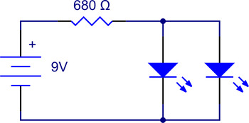 |
The wrong way to use LEDs in parallel. |
|---|
You might have seen this done by bad engineers or people who don’t really know what they are doing, and sometimes, you can get away with it. Like the single LED circuit, this arrangement can be quite forgiving if your only criterion for success is that both LEDs turn on. However, it is good to understand why doing this is bad in theory and how it can cause you a lot of subtle problems in practice.
The basic assumption that is not explicitly stated is that both of the LEDs are identical and that the intent is for them to behave the same way. However, LEDs generally won’t be exactly identical, and because LEDs have an exponential relationship between voltage and current, small differences in the voltages applied to them can make a big difference in the current they draw. (That’s why we needed the current-limiting resistor in the first place, so that we could set the current with the resistor instead of getting the voltage just right.) If you took two ideal diodes that just turn 100% on at 2.1 V and 2.2 V and put them in the circuit above, the 2.1 V diode would carry all of the current, and the 2.2 V unit, since it only has the same 2.1 V applied to it, would be off and conduct no current. Real diodes are not quite as extreme, but you can get close to it, especially if you are using LEDs with different colors.
So, why does it matter so much that the LEDs don’t share the current equally? The main problem is that you have little control over what is actually happening in your circuit. The resistor, which originally let you set the current for the single LED, now just sets the total current that all of the LEDs together consume. Since it is unlikely that the LEDs will share the current evenly, that has several ramifications:
- The LEDs might not look evenly illuminated, which might just look ugly or not inspire confidence in your creations. The approach also won’t work with LEDs of different colors. If you have this problem, at least you can see it and do something about it.
- If you make several copies, you might have substantial variation from circuit to circuit, which can cause a lot of confusion if that variation affects some other part of your system. Also, the first problem might crop up at a bad time: your prototypes could have had well-matched LEDs, giving you confidence to make many more units that turn out to be visually unacceptable.
- The uneven distribution of current in the LEDs could lead to premature failures. This can be especially likely if there are many LEDs in parallel, since you could have one LED drawing several times the current you intended. And, once the first LED burns out, there are fewer LEDs to share the same total current, and the second and third LEDs will burn out faster and faster.
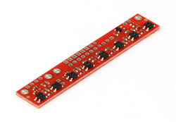 |
QTR-8A reflectance sensor array. |
|---|
- If your LEDs are not just for humans to see, the variation in brightness you do not notice can have big impacts on your system’s performance. The most extreme yet common example is infrared LEDs, which we use in all kinds of sensors. We can’t see the variations in brightness, but it will definitely make a difference to your array of reflectance sensors.
I was originally going to take some pictures of several LEDs in parallel to show the problem, but the first several I grabbed turned out to be remarkably uniform. The brightness seemed so similar that I tried measuring the currents, and even those were within 1% of each other. That’s the kind of result that makes you think the wrongness of this approach might be exaggerated. However, a few pairs of LEDs later, I came across a pair of yellow, high-brightness LEDs with almost a 2:1 ratio in their currents:
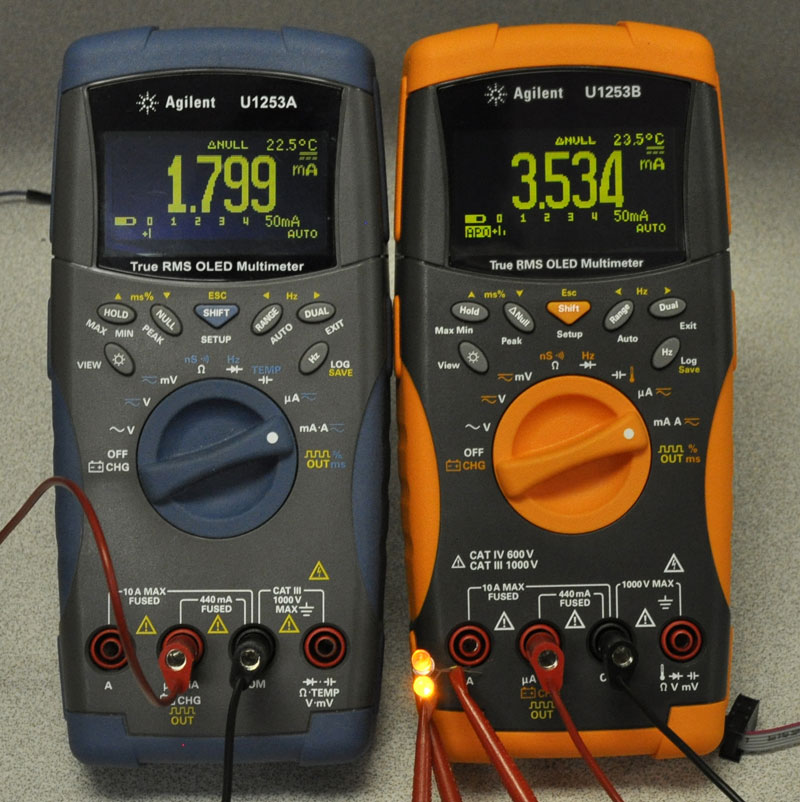 |
Current meters showing different currents through parallel LEDs. |
|---|
It’s also notable that I could not tell the difference in brightnesses. In the picture, the lower LED is the one with less current, but it looks brighter because it’s better aimed at the camera. While I’m confident that we could determine the brighter one if we tried (maybe shining them through a sheet of paper), the point is that this kind of variation is easy to miss even if you’re looking for it.
Since the basic problem with the LEDs being directly in parallel is the lack of individual current control, the easy solution is to add a current-limiting resistor for each LED:
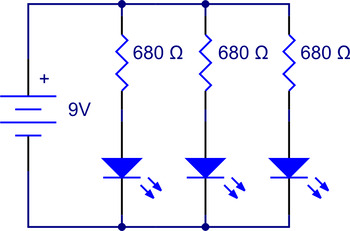 |
With the separate resistors, each parallel pair of LED and resistor are now effectively independent, and all of the abstractions that worked for us before work for us again. However, while there is nothing really wrong with this circuit in terms of working reliably and as expected, it is usually not the best way to connect three green LEDs to a 9V battery because it uses three times as much power, even though most of the power is wasted in the resistors. Putting the LEDs in series, with a single resistor, would give us a solution three times more efficient:
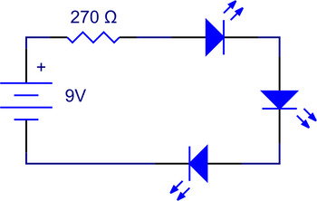 |
Since the LEDs are all in series, they are guaranteed to have the same current and so should have very similar brightnesses. We can also safely connect LEDs of different colors this way, as long as they have the same recommended operating currents. The main drawback to this approach is that we cannot keep adding LEDs as easily as in the parallel case. With three LEDs, we’re expecting about 2.7 V on our resistor; with four LEDs, the voltage would be under a volt, and with five LEDs, the LEDs would stop lighting up. Even with the three LEDs, our brightness is now much more dependent on the battery voltage: if the battery gets drained to 6 V, the LEDs will get dimmer than if the battery drained to 3 V in the parallel case.
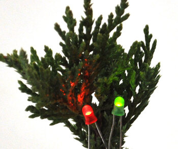
If we do want to connect five LEDs to our battery, we might settle for a combination of three series LEDs in parallel with two LEDs in series. Each series string will have its own current-limiting resistor, and at 9 V, each LED would get about 10 mA:
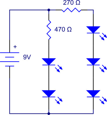 |
One drawback is that as the battery voltage drops, the three LEDs will get dimmer more quickly than the two, but that’s probably acceptable if these LEDs are just for decoration. If you want to mix colors, using red for the three LEDs (with a slightly different resistor) and green for the two would make the LED voltages closer (about 4.2 V for the two green in series vs. about 5.4 V for three reds in series) and therefore result in more consistent dimming as the battery drains. If you want five IR LEDs for a sensor array, you might want to regulate the voltage to the LEDs to limit the dependence on the battery or other supply voltage. In the case of the 3pi robot, we have five IR LEDs in series from a regulated 9.25 V for consistent operation. (IR LEDs have only about a 1.2 V drop on them, so five in series have a combined drop of 6 V, so we can light them from 9 V, unlike five green LEDs.)
You might want to connect pairs of LEDs in parallel but with opposite polarities. I like doing that with different color LEDs on motor driver outputs, so that you can see which direction the motor is supposed to be turning. I recently saw this done the wrong way:
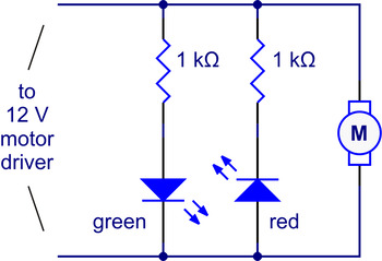 |
Wrong way to connect anti-parallel LEDs. |
|---|
This situation is different from our previous ones because that assumption I made explicit at the beginning, that we want the LEDs to behave the same way, no longer holds. Now, we want only one LED to be on at a time, so even though they are electrically in parallel, we’re counting on the diode functionality to effectively disable one of the parallel branches and leave just one current path through one LED. The circuit would work fine with ideal diodes, which can take arbitrarily high reverse voltages, though it would be inefficient in its use of the extra resistor. However, LEDs typically have fairly low reverse breakdown voltages, and they can start conducting again at voltages well below 12V. The reverse LED current would still be limited by the LED’s resistor to less than the current drawn in the forward case, so this reverse current might not destroy the LED, but it’s still poor engineering to use extra parts to end up with a design that unnecessarily puts components under excessive stress.
In this case, we want to put the LEDs directly in parallel, so that we need just one resistor and so that the voltage on the reverse-biased LED never exceeds the forward voltage drop of the other one.
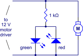 |
You can even get bidirectional or bi-color LEDs that have two LEDs in a single package with two leads, just for this kind of application.
So, keep these things in mind when you’re scrambling to make some last-minute geeky decorations or making someone a present covered in LEDs. After all, if you’re subjecting your special someone to that kind of gift, the LEDs should at least light up evenly. Merry Christmas!
 |
-
Otimização Do Algoritmo De Maze Solver Para O Robô Pololu 3pi
- 20 December 2010Customer Ana Paula Almeida wrote this Portuguese-language paper about the 3pi Robot (1MB doc) as part of a Master’s program in Computational...
-
Baby Orangutan Useless Machine
- 27 December 2010This video shows a “Useless Machine” controlled by a Baby Orangutan. It counts how many times the button is pressed, and then the arm comes out...
0 comments
Post a comment


Home | Forum | Blog | Support | Ordering Information | Lists | Distributors | BIG Order Form | About | Contact
© 2001–2026 Pololu Corporation


