Pololu Blog » Engage Your Brain »
Parallel circuits
If you have a limited or informal electronics education, parallel circuits might be the kind of topic you glossed over or have forgotten about. After all, parallel circuits sounds like boring theory, and you want to get to the fun stuff. But, banging your head over a simple system that you think should just work isn’t much fun, and you can save yourself a lot of grief with a bit of awareness about the potential differences between a schematic and a physical circuit. Also, I’m a proponent of learning fundamentals and trying to really understand things, so we’ll start with a bit of the basic theory.
Electronic components or subcircuits are in parallel when they share pairs of nodes. A node is an abstraction for a connection among multiple parts, and we simplify our description of the circuit by assuming that even though the connections don’t happen at a single point, the voltage is the same everywhere along that node. The simplest parallel circuit is a pair of resistors with their leads connected, forming two nodes:
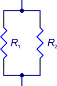 |
Without anything else, you could also claim the two resistors were in series in the sense that the circuit is a single loop, but there are only two nodes to this circuit, and relative to those, the two resistors are in parallel. Without any power sources, nothing happens, anyway, so let’s add one to the circuit:
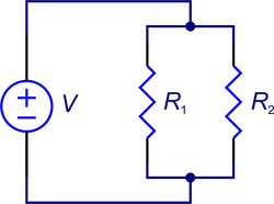 |
As I’ve drawn it, the schematic is a bit strange in that it belabors the equivalence of the two resistors relative to the voltage source. We can redraw the schematic in its more typical form:
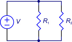 |
If you think of the schematic as representing the actual layout of the physical circuit, it might be more representative of reality, in the sense that the wires for R1 also carry current for R2, but R2 has extra wires that carry current only for it. However, the schematic only represents the conceptual connections, so we could swap the locations of R1 and R2, and the schematic would be just as valid even if in reality, R2 is farther from the power supply than R1. These two diagrams are therefore equivalent representations of the same circuit:
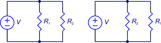 |
Clearly, you should not assume that the way the components are arranged on a schematic is indicative of the physical embodiment of the circuit.
We are not limited to just two components, to only resistors, or even to individual components. Here, I added an LED, a capacitor, and a motor to get more elements in parallel:
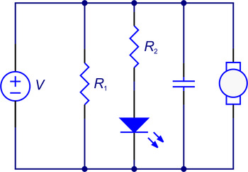 |
Note that in this case, R1 is not in parallel with R2 since they do not share nodes; however, R1 is in parallel with the combination (in a series circuit) of R2 and the LED.
However, to get in some basic theory, let’s go back to our simplest case, with the two resistors. If you have any electronics experience or have done some plumbing or irrigation work, it should be intuitively obvious that the current out of the voltage source is the sum the currents in each of the resistors. This is more generally covered by Kirchhoff’s current law, which goes with his voltage law that I mentioned in the first LED circuit post. Basically, for any node, all the current going in must equal all of the current going out; otherwise, we would have current coming out of nowhere or disappearing into nowhere. Consider the node with currents labeled as follows:
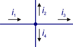 |
We would say that i1, the current going in, is equal to the sum of the currents going out: i1 = i2 + i3 + i4. (A little nit-picky note to point out is that the node is not just the dot in the middle of the four line segments: the line segments and dot are all part of the same electrical node.) We could have decided we wanted to label i2 going into the node:
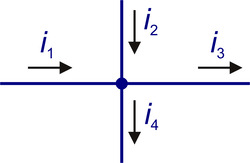 |
In that case, our equation would be: i1 + i2 = i3 + i4. For those concerned about directions of currents, you can see that this equation can be rearranged as i1 = i3 + i4 – i2, which can further be arranged as i1 = i3 + i4 + (- i2 ), which is the same as our equation for the first diagram, just with the sign on i2 inverted, which makes sense because we have drawn the arrow in the other direction: i2 flowing up is the same thing as - i2 flowing down.
Using only Ohm’s law and this knowledge that the currents must add up, we can easily derive the equivalent resistance of two resistors in parallel. If you mostly know this, I recommend you actually do the calculation for yourself as a quick exercise before reading on; if this is new for you, try to really understand it to the point where you can reproduce it and calculate the more general formula for any number of resistors in parallel. Here is the circuit again, with the currents labeled:
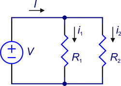 |
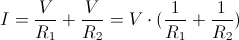
Because we have only two resistors and the voltage source in parallel, there are only two nodes in the circuit, so there can only be one voltage we care about, which is the voltage between the two nodes. That voltage is V, which is imposed by the voltage source, whose sole purpose is to make the voltage V no matter what (we don’t get to have ideal voltage sources in real life). Since each of the resistors has V volts across them, the currents in the resistors are V/R1 and V/R2. The current out of the voltage source, I, is the sum of the two: I = V/R1 + V/R2. We can factor out the V to get to:
 |
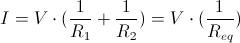
When we are looking for an equivalent resistance, we are looking for the resistance, Req, that a single resistor would have to give us the same current. A single resistor would give us a current of V/Req. If we compare that to our final result for the parallel resistors, we see that:
 |
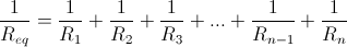
Therefore, we see that 1/ Req = 1/ R1 + 1/ R2, or more generally for any n resistors in parallel,
 |
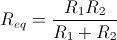
For completeness, we can solve explicitly for Req in the original case with two resistors:
 |
You should also have an intuitive understanding of what happens to resistors in parallel. Every time you add a resistor in parallel (put it “across” the existing circuit), the equivalent resistance will go down since more current will flow. As a corollary, the equivalent resistance of several resistors in parallel will always be less than the smallest resistor. If you put two resistors of the same resistance in parallel, the equivalent is half the resistance; if you put three, the equivalent is a third. If you put a very large resistor in parallel with a small one, the large one won’t affect the circuit much.
All of this parallel resistor stuff usually doesn’t cause much trouble, but the real problem that people encounter all the time with parallel circuits is that everything we build is actually massively parallel, leading to huge nodes with dozens or hundreds or thousands of connections. And the bigger the nodes physically get, the more invalid the abstraction of calling the voltage the same everywhere along the node. Let’s consider the larger parallel circuit again (I replaced the voltage source with a battery to make this a bit closer to what you might actually build):
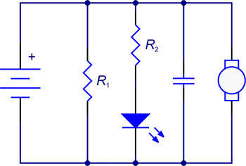 |
This circuit is much more than just two resistors, and yet it still has the same two main nodes (there is a third node between the LED and resistor). You can interact with the circuit in two main ways: you can do something with the spinning motor, and you can look at the LED. We want to think of those two features as independent, but if you vary the mechanical load on the motor, it will vary how much current it draws and in turn affect the voltage applied to the other components of the circuit (not just because the battery voltage will vary, but also because of varying voltage drops along the wires), possibly resulting in noticeable variation in the LED brightness. The two elements are coupled, even though we don’t want them to affect each other. You might notice the same thing if you plug a vacuum cleaner into the same outlet as a lamp.
The main reason I want to emphasize the problem is that our popular nodes, such as the power rails, usually have so many connections that just drawing the lines showing the connections becomes unwieldy. We fix that problem by taking away all the lines and just labeling the connections. The same circuit as before would therefore more typically be drawn as follows, especially if this represents only part of an even bigger system:
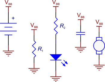 |
Obviously, this kind of representation makes it even easier to forget how interconnected our circuits are, even though we usually try to think of the subcircuits or components separately. With something as limited as this example, it is easy to notice the correlation of the motor load (which you can probably notice from the sound changing) and LED brightness; it gets harder when you have many parts, many of which don’t as conveniently indicate their operating status. Going from a correct schematic to a successful physical embodiment therefore often takes more skill than just making all of the indicated connections, and when you are troubleshooting a circuit that doesn’t work as expected, one of the things you should think about is how many things you have in parallel.
-

Simple LED circuit abstractions
- 8 December 2010The simple LED circuit from last time is a great first circuit for everyone interested in electronics because it is so forgiving. If you connect...
-
Otimização Do Algoritmo De Maze Solver Para O Robô Pololu 3pi
- 20 December 2010Customer Ana Paula Almeida wrote this Portuguese-language paper about the 3pi Robot (1MB doc) as part of a Master’s program in Computational...
0 comments
Post a comment


Home | Forum | Blog | Support | Ordering Information | Wish Lists | Distributors | BIG Order Form | About | Contact
© 2001–2024 Pololu Corporation


