Pololu Blog »
New Product: 5V, 5A Step-Down Voltage Regulator D24V50F5
 |
Remember the post I wrote two weeks ago about our tiny D24V25F5 voltage regulator and some of the testing that we did on it? Well, we were so happy with how that regulator turned out that we decided to make a higher-power version with a larger inductor and beefier MOSFETs. This new regulator is the D24V50F5, and while it is only 0.1″ bigger than its 2.5 A cousin, it can deliver 5 amps!
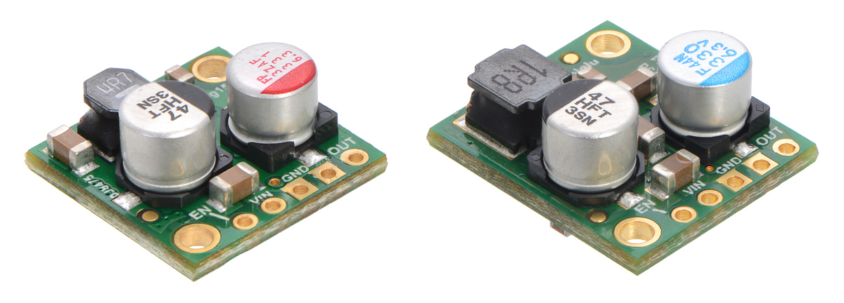 |
Side-by-side comparison of the 2.5A D24V25Fx (left) and 5A D24V50F5 (right) step-down voltage regulators. |
|---|
You can see the bigger MOSFETs on the bottom side:
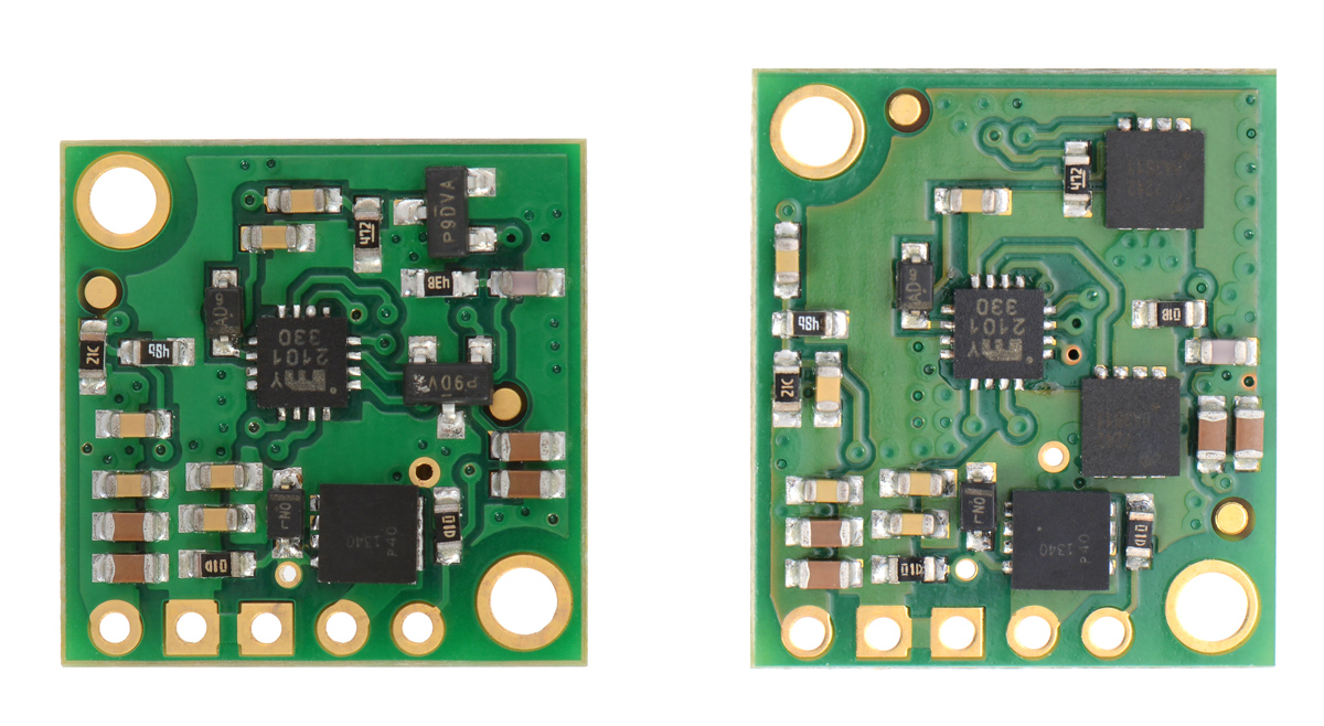 |
Comparison of the D24V25Fx (left) and D24V50F5 voltage regulators showing larger MOSFETs on the higher-power board. |
|---|
The D24V50F5 can also take inputs up to 38V and has typical efficiencies of 85% to 95%. It’s amazing how much power these little 3×3 mm MOSFETs can handle, and with its compact size and high power, this regulator is our new favorite.
Related products


-

Creepy eyes Halloween prop
- 3 October 2014In the lead up to Halloween, I thought it would be fun to make some Halloween-themed props; in particular, I was interested in making something...
-

Polo-BOO! Halloween Sale
- 6 October 2014Halloween is just a few short weeks away, and that means it’s time to start making an awesome costume or building an extravagant yard display...
35 comments


Thanks for pointing that out. While the 3A header ratings are probably fairly conservative, you should solder wires to the regulator if you want to push it to its limits. Current limits or ratings in general are quite complicated for products like this since there are so many factors to consider, including ambient temperature, airflow or lack thereof, how many other contacts or heat-generating components are nearby, and what kind of duty cycle is necessary.
We expect to be updating these regulator pages and perhaps to be adding other resources to help specify and clarify what kind of performance you can expect at various operating points.
- Jan

Sorry, we don't have those characteristics well characterized since they vary a lot with parameters like load and input voltage. We do not especially optimize for ripple, but it will generally be under a few hundred millivolts peak to peak. The switching frequency changes with load, but the highest frequency is around 600 kHz.
-Claire

Is there any benefit in bolting this device down using the mounting holes - I mean are the plated thru mounting holes in any way connected to the ground plane and would bolting the unit to a large area of copper help dissipate heat away from the device?
We do not have a particular maximum operating temperature rating for these regulators. In general, as the temperature goes up, the lifetime of various components goes down. Among the components likely to limit lifetime are the larger capacitors, which have a rating of 2000 hours at 105 degrees C. However, other components typically get much hotter than the capacitor, and the temperature distribution across the board depends on many factors, such as ambient temperature, load current, and input voltage.
If you are seeing only 50 degrees (how are you measuring that?) with 12 V in, 14 V should be fine. How much current are you drawing?
The mounting holes on these regulators (and most of our other boards) are not electrically connected to ground or any other node in the circuit. If you want to mount the regulator to a heat sink with maximum effectiveness, you should probably use some thermal gap-filling material so that the side with the low-profile components can conduct heat into your heat sink. Be careful not to short anything out on the heat sink!
-Claire

I want to use the D24V50F5 regulator to power a raspberry pi2(5v 700ma) and a raspberry pi3(5.1v 2500ma) on a mobile robot. the power source will be LiPo battery (for high currency ability).
Is this going to work? if so, what LiPo battery specs do you recommend?
I am a software developer. My knowledge of power supply and electronics is very limited. I hope my question is clearly stated.
Thank you and best regards,
-David
The D24V50F5 should be able to handle the combined ~3.5A draw of your Raspberry Pis. I don't have any specific recommendations for a LiPo battery, but anything 2S or more that has enough instantaneous current output and capacity for your application should be fine. If you are new to selecting batteries, this blog post about battery capacity might be helpful. If you have more questions about how to use that regulator in your project or general electronics questions, you might consider posting them on our forum.
-Claire

I can see the dxf but a PDF with the actual locations would be great to have.

The mounting holes on the board are 0.85" from edges they are closest to. We do not have a dimension drawing for this board yet, but the DXF file has all the hole locations on the board.
-Grant

just out of curiosity: how does the board work?
Are you using a micro controller with custom firmware (that Y2101 330 thing on the bottom side) to control the MOSFets?
Sorry if that questions sounds stupid (I'm not really into buck converter design).
Thanks and kind regards,
Paul
The regulator does not have a microcontroller on it. It uses an IC designed specifically for controlling the circuitry of a buck regulator.
-Claire

Re: D24V50F
Can you provide some detail on the ENable function, trigger voltage threshold and if possible a typical simple wiring schematic.
Many thanks.
David
Details for how the enable pin functions and its threshold can be found in the "Connections" section of the D24V50F5 regulator's product page.
-Claire

This is one of the ones where we do not disclose the schematic.
-Claire

What reverse voltage can the 5 Volt output withstand? I would like to connect it to a 12~15 V dc rail so that the 5 V is still present when the 12~15 V is off. Would a reverse blocking diode be required?
Thanks,
Brewster
It is generally bad practice to directly connect two voltage sources, so you should implement something to isolate your 12-15V rail from the output of the regulator. Appropriately rated diodes could work for that. Even when the regulator is off, it is not good practice to connect another voltage to the output, and you should definitely not connect more than 5V.
-Claire

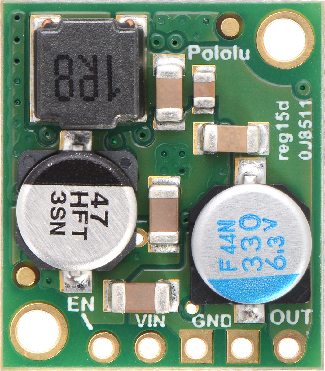
I noticed that you are using Micrel MIC2101 IC for the buck controller. Your inductor is 1.8 uH (1R8 in the image) but in the Micrel datasheet says that for a Vout of 5 V, a Iout max o 5 A and a Vin max of 38 V and a switching frequency between 200 and 600 kHz the inductor should be between 9 and 22 uH. How is this possible? Am i missing something? For 1.8 uH only if Vin is at the minimum of 6V but the equation states Vin max (not Vin min).
There is no single optimum inductance for all operating points, and in general, we need some balance of inductance, size, resistance, etc. for boards like ours that are intended to work over a wide range of operating conditions. We did lots of testing with that regulator and Micrel's evaluation board (which uses a 1.5uH inductor) to find the best values for all of the components within the constraints we were working with.
-Claire

Have you done any thermal testing at maximum specified load, or is that really just an electrical spec?
Thermal resistance of FET junctions to ambient? How do I know sure the devices won't get too hot? There are generally approximations for Theta ja when pcb land areas are used as the only heat sink. Have you analyzed how much temperature rise the FETs will have at max load?
The RMS ripple current in the inductor windings will be higher than the output current, won't it?
At 36V in, the output current limit is just under 2.5A. The temperature levels off at about 140C with the inductor being the hottest part. The inductor's ripple current is high, but not higher than the output. By the way, we have some more characterization available on this similar product:
https://www.pololu.com/product/2866
That board has a 1.5uH inductor on it, and with 36V in and 2.5A out the RMS ripple of the inductor is about 1.35A.
-Claire

I would like to use this step-down regulator with the Dual MC33926 Motor Driver #2756 to power a RPi 4B (which needs 5V up to 3A). Is it compatible with the board?
Also, I don't see a heatsink and I am afraid it could overheat. Is there a risk?
Thanks
-Claire

Thanks for this, it solved my battery powered raspberry pi voltage problems.
I am wondering about the Enable pin. The instructions say it's pulled up to VIN and can be driven low to shutoff. My VIN is about 8 volts. Would I fry a microcontroller output pin (such as arduino or raspberry pi) if I tried to connect it to ENABLE, since ENABLE is pulled up to 8 volts instead of the microcontroller's 3.3v/5v?
I'm thinking maybe I need to use a Pololu power switch for this, but I was wondering if I could get away with using the Enable pin directly.
Thanks

Microcontrollers usually have a diode going from each I/O pin to its logic supply. These diodes clamp the voltage on the pins, preventing pull-up resistors like the one on the D24D50F5 board from pulling the pins too high (and the resistor limits the current through the diode), so it is probably fine. However, if you want to be extra safe and not rely on the clamping diodes, you could remove the pull-up resistor from the regulator. The pull-up resistor is the small black component labeled "01D" near the mounting hole in the bottom right-hand corner of this picture of the underside of the regulator.
Brandon

The D24V50F5 regulator has short-circuit protection, and a supercap looks like a short, so the regulator will just keep trying to restart out of short circuit protection. I tested one on a pair of 150F, 2.7V caps in series, and the regulator did eventually charge them to 5V in about six minutes, for an average output current of about 1A. One thing to be aware of is that once the caps charged enough so that the short-circuit cycle stops triggering, the current jumped pretty drastically before ramping down.
So, overall, it's possible but not recommended since you would be better off with a regulator that doesn't have the short-circuit protection and can continuously deliver its intended current into your supercaps.
-Claire

It is possible to slightly adjust the output of the D24V50F5 regulator. Please email us for more details.
-Claire

I see from your response on 13Jul 2021 that it is possible to raise the output to ~5.2 V?
“ It is possible to slightly adjust the output of the D24V50F5 regulator. Please email us for more details.”
I would like to do the same, for the same reason, overcome losses downstream of the regulator (and get rid of that darn lightning bolt 🙂). I’m sending an email message as follow up.
Thank you,
Patrick
We saw your email and responded to it. Hope that helps your issue!
-Claire
Post a comment


Home | Forum | Blog | Support | Ordering Information | Wish Lists | Distributors | BIG Order Form | About | Contact
© 2001–2024 Pololu Corporation
